A different opposed piston engine---

Home Model Engine Machinist Forum

Help Support Home Model Engine Machinist Forum:

This site may earn a commission from merchant affiliate links, including eBay, Amazon, and others.
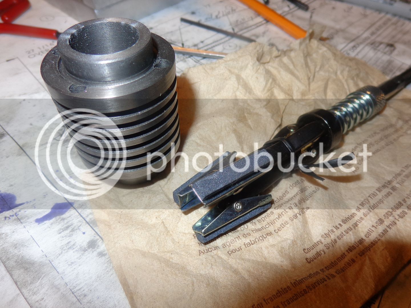
Hmmm--Not a particularly good start to the morning!! My new Powerfist brake cylinder hone which is supposed capable of fitting 3/4" to 1 1/8" brake cylinder bores---There is no way in Hell that it is going to fit into a 3/4" bore. RATS!!! I guess these cylinders will move directly from "reamed" to "lapped"
 
Well--I didn't get quite as many parts made as I thought I would this morning (I seldom do)---But---Progress was made. Cylinders got lapped, rocker arm support and rocker arm and push rod got made and test mounted.---But DANG-- I didn't know it was this dirty before I took the picture!!!--NOTE TO SELF---Blow off with air hose BEFORE taking pictures!!

 
Today I made the exhaust pipe and bracket, the two connecting links that attach the pistons to the arms that my friend in Alabama is making, and the intake manifold. I haven't made the pistons yet because I am waiting for a piece of tooling that I had to order to finish them. There are MANY strange angles on that intake manifold, and the batteries are dead on my digital angle finder, so I did it the "Old School" way by scribing layout lines and "milling to the line" as I went along.

 
Todays offering to the machine Gods is a tiny pair of connecting rods. These are the rods that connect the crankshaft to the two pieces that JNCW in Alabama is making for me. They don't look like much, but I have spent nearly all day making them.---I tried to get a picture of them "in place" on the engine, but its just getting too crowded in there to show very much.---
-Brian

 
When I get to the point of ordering my cdi ignition from SNS engineering, I will now have a place to mount the magnet and the D-tube which holds the Hall Effect sensor. Why is there layout dye on the intake manifold?--Because when I got it bolted into place, I seen that I had missed machining one of the weird angles when I had it in the mill. The dye just helps me to know which face the weird angle goes on when I put it back up in the mill. I have been waiting for a long 1/4" ball nosed endmill to come in so that I can go ahead and finish the pistons. It came in this morning, so I guess the pistons are the next thing I am going to work on.
 
Brian-

I'll ask because I don't know....could you have fired this engine by using a glow-plug, if you wanted to? If yes, why did you choose a sparker, over the glow-plug?

Just curious. If I don't ask, I can't learn. Also, at what point in the designing phase, did you decide on using the Hall ignition system?

The build becomes more interesting as it progresses to the obvious conclusion.....a video of the engine running.


Frank
 
I can't give a good answer about glow plugs, because I have never used one. I THINK they depend on the engine having a high compression ratio like a diesel, but that is only guesswork. Why did I go with a cdi ignition?--Well, I added up the price of a set of ignition points, a condenser, a 12 volt coil--and that came to about $75.00--and that doesn't take into consideration the $100 or more you would spend on a 12 volt car battery to run things. The complete cdi set up cost about $100, including 4 small rechargeable batteries about the size of small flashlight batteries and a recharger. That was my reasoning.
 
This is piston #1 in the chuck. A whole lot of hogging off material to get from the 1.6" diameter piece of grey cast iron down to .875" diameter. I did this with an indexable carbide, and cut the piston to about 3/8" longer than what the finished length was going to be. Once I got it down to .875" diameter, I switched tools to a newly sharpened HSS cutter, and took it down to the finished diameter of 0.750" using a lathe speed of 970 rpm.--Of course the last 5 or 10 cuts were done with much breath holding at .001" to .002" depth of cut.--I have ruined so many parts by turning them undersize that this is always a very scary thing for me. At this time I also put the counterbore in the end of the piston using a drill, then a 1/2" diameter 4 flute endmill, then a carbide boring tool. After reaching the diameter I wanted, I used a 0.093" cut off blade and plunge cut to a depth of .056" for the o-ring groove. This is what the o-ring book recommends, but if its not deep enough I can turn it a bit deeper later. I won't know for sure until I assemble the piston in the cylinder and see how "tight" it is with the groove at this depth. Next step was to move the cut off blade up to the finished length I want the piston to be plus about 0.030"and plunge cut about 0.060" deep. I will take the part out of the lathe now and finish the cut on my bandsaw, then put it back in the lathe and face that sawcut end off until the exact length is reached.
 
With the piston cut to length in the saw, then faced off in the lathe, the next step will be to put the slot in the bottom of the counterbore that the connecting rod fits into, and to drill the cross hole for the wrist pin. The piston will fit into the cylinder now, but if you push it through with your finger you can feel a few rough spots. The piston will be coated with 600 grit carborundum paste and worked back and forth until any roughness is gone.
 
JWCNC--What's the status of the two arms you were going to CNC for me? I'm running out of things to machine up at this end. Once I get these pistons sorted out, I only have the timing gears and valves left to tackle.---Brian
 
There are a couple of things worth talking about in this picture. The first and possibly worst, is that once I have milled the 1/4" slot in the piston for the connecting rod to fit into, there is absolutely no good way that I know of to ensure that I am drilling the wrist pin hole at exactly 90 degrees to the slot. What I resort to, is sticking the con rod into the slot (You can see the end of it sticking out of the piston) and then setting my machinist level on the bit that sticks out, then rotate the rotary table until it is right "on the bubble". This gets me "pretty damned close", but I wish I had a better way of doing it. The second point, which is pretty obvious, is that when the chuck jaws are positioned to give the drill and reamer good access from the top, the bottom jaw of the chuck is always in the way, so I can drill and ream "almost" all the way through, but have to finish it up in my machinists vice.
 
The pistons are finished. I am always somewhat amazed that parts so small could take such an immense amount of machine shop time to make. I spent a lifetime as a design engineer wondering what in the name of #$@^ was taking so long for my machinist to make a few simple pieces. Now I know---My apologies go out to every machinist that I ever thought was "dogging it". I'm starting to run out of pieces to build. I will leave the valves and cages to the very last moment. I know I can make them. I've made them a number of times before. It's just that they are such hateful damn things to make that I will make everything else that I can first. Probably work on timing gears and exhaust cam tomorrow.

 
Hi Brian:

Watching your build with great interest - as usual.
With regard to your drilling the hole in the piston. Try using that nice slot in the mill table. Lay the piston along the slot, put your connecting rod inside like you have it and use shims under the rod such that when you clamp the rod down it rotates the piston so the slot is parallel to the table. Or use a very narrow clamp or piece of scrap that will go up inside the slot and wiggle the piston while you tighten it to rotate the piston.
Then clamp the piston directly to the table slot and release the rod (or clamp) on the slot.
Use an edge finder or indicator to indicate the side of the piston and from there you can move over the right distance to be over the centerline of the piston. Same way to find the position of the hole from the end of the piston.
Using the slot will give you some space below for the drill and reamer to pass through the piston.

In the end it really makes little difference if the slot is turned slightly. It only results in the piston be being rotated slightly. Presumably you have a bit of side play in the slot so the rod can float a bit. You should.
What IS important is that the hole is right on the center line of the piston.

I've just finished making a 2.5" diameter aluminum piston for a Parcell and Weed hit-miss engine circa 1902 using this method.
I've thought about documenting the build here but that takes a lot of time. I've been taking pictures.

Thanks for your efforts in documenting your build.

Sage
 
Hi Brian:

Another comment on the piston.
Why is the hole so far near the top? Do you have any clearance issues with the rod on the inside of the piston? I assume you can animate the engine to check that sort of thing. Admittedly the geometry of this particular engine is weird so I guess it works.

The hole is usually at or below center to give the rod more room to oscillate back and forth.

Nice CAD work BTW.

Sage
 
Sage--This engine has some weird geometry, plus the fact that there is a slot at the rear/bottom of each cylinder that the big rocker arm fits up into. In a perfect world, the piston only needs to be slightly longer than its own diameter (to keep it from "cocking" in the cylinder.) This piston is extra long because it needs the extra support when its at bottom dead center. The lower half of the skirt extends right out over the slot.
 
Sage--This engine has some weird geometry, plus the fact that there is a slot at the rear/bottom of each cylinder that the big rocker arm fits up into. In a perfect world, the piston only needs to be slightly longer than its own diameter (to keep it from "cocking" in the cylinder.) This piston is extra long because it needs the extra support when its at bottom dead center. The lower half of the skirt extends right out over the slot.


Hi Brian,

Gus trying very hard not to build this engine. Alas !!! My spirit is strong but mind n body is weak.

Trust all is well by now and winter is about over.
 
Hi Gus--Always good to hear from you. I wouldn't recommend anyone building this engine until I see if it is going to work. As for winter--Its just getting started good. Snow came and stayed in mid December, we have been having blizzards for last week. Schools closed, highways closed, police warning everyone not to travel unless its an emergency. Currently have 20" of snow, -25 C at nights. It will stay very cold with snow thru February and March, then start to head into spring about half way thru April. The ice generally goes out of the local lakes around the 23 April.
 
I don't suppose this job is intended to run very fast, but it did occur to me that the fatter push-rod now has much more inertia than the other valve-train components. You could ease the job of the valve spring quite a bit by making the push-rod hollow. Just a thought.
 
Back
Top