First and Third Projection Symbols

Home Model Engine Machinist Forum

Help Support Home Model Engine Machinist Forum:

This site may earn a commission from merchant affiliate links, including eBay, Amazon, and others.

GreenTwin

Well-Known Member
Staff member
HMEM Supporting Member
Global Moderator
Joined
Jul 2, 2021
Messages
3,451
Reaction score
1,411
Location
MidSouth, USA
I have been drawing professionally for 29 years, both manually on the drawing board, and on computers.

Recent discussions involve mixing up symbols for first and third projection.

I have to admit I have never used these symbols, and would not know what they look like if I saw them.

Can somebody post a drawing that shows those, preferably a model engine drawing.

Thanks,

.
 
In the drawings I create for work and for model engines, I like to envision an exploded view of an engine, and then arrange all the parts on the drawings in the approximate order that they are seen in the exploded view.

And I like to draw parts so that their mating surfaces are facing each other, often stringing several mating parts together across the sheet.

So I guess I sort of use a "what you see is what you get" approach.

For equipment in buildings, I draw things on the sheets as if I were looking down on the building from overhead, so that someone looking at my drawings does not need to physically rearrange the orientation of the equipment in their head in order to understand the adjacencies of equipment, how it is fed, and how the process flows.

Some engine drawing sets (and building/equipment drawings) that I have seen are drawn as if a bomb hit, and the parts are just scattered randomly.
There may be a valve next to a flywheel, with the valve springs many sheets away.
I would guess some folks just start drawing parts on sheets in the space available, with no consideration of organization, or grouping of related items/adjacencies.

For large working projects, it is a matter of necessity to rigorously organize things, else the project will quickly get out of hand.
And many others who are only marginally familiar with the project have to review my drawings, and so it must be clear to them, whether they are technical people, or layman.

And I like to spread out things on the sheet to allow for changes that occur during the design process.
I never try to fill up every inch of real estate on the page, but that format style does have its followers in some circles.
Rule #1 of drafting and design (for me anyway) is "Never paint yourself into a corner. Maintain elbow room at all times".

I must have been asleep in drafting class they day they taught symbols for first and thrird angle project.

.
 
3rd.JPG
 
Well, I see the symbol, but I guess I am just clueless, because that means nothing to me.

What exactly does that symbol mean as related to the drawing sheet upon which it appears?

If I went to a psychiatrist, he would probably say "Is the symbol in the room with us today?", "Can you see the symbol now?", "Is the symbol saying something to you?".

My answers would be "Yes, Jason just brought it into the room", "Yes I see the symbol on the sheet", and "No, the symbol is not talking to me; it says nothing to me".

.
 
Last edited:
Well it tells you what side of the part represented by the tapered symbol is on which side of the end elevetion represented by the two concentric circles.

Had the thick end of the taper been next to the circles you would be looking at the opposite side of the part and 1st angle would have been used.

Ist at the top 3rd at the bottom. I've added the flat to show the dfferences better. Green eye shows which side the part is being viewed from when the tapered elevation is drawn
projection eye.JPG
 
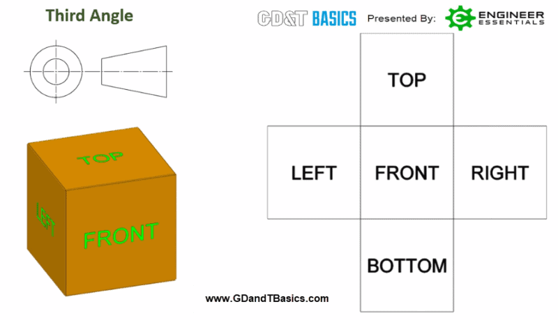
Third angle projection can be visualized by “unfolding the box,” as if the object itself is being unfolded to show the views from each side. Figure 1 shows the views of a cube being represented by third angle projection.


Third-Angle-Projection-Views-800x459.png

Third angle views are intuitive, as they represent you looking at the object from the corresponding side. The front view is always shown in the center. The view of the object from the right is shown to the right of the front view, the view of the object from the left is shown to the left of the front view, and the top and bottom views are shown above and below the front view, respectively. If we needed to show the view from the back, the back view would be placed below the bottom view.

Quick Note on representation of the symbol for third angle. There are actually four ways Third Angle Projection can be represented on a print and all of them are acceptable (figure 2). The big takeaway here is it does not matter if the “side” view of the “cone” is on the right or left. For Third Angle Projection the “pointy” end of the side view of the cone in the symbol is always pointing towards the front/”circle” as shown in Figure 2 below. All four of these are perfectly acceptable for third angle:

1706006057479.png

First angle views are less intuitive. They can be visualized by “tipping the box over.” Figure 2 shows the views of a cube being represented by first angle projection.

First-Angle-Projection-Views-800x450.jpg

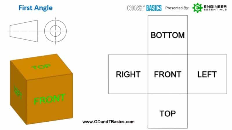
The front view is shown in the center, just like in the third angle projection. To place the view of the right side, you must tip the box so that the right side is facing you. To do this, the box must be tipped toward the left. This results in the right-side view of the object being located on the left side of the front view. With the front side facing you once more, tip the box to the right, and you will have the left side facing you. So, the left-side view will be located to the right of the front view. This same method is used for top and bottom views. With the front of the object facing you, tip the cube downward. You now have the top side facing you, with the top view being located under the front view on the drawing. By tipping the front view upward, the bottom view of the object is facing you, with the bottom view located above the front view.

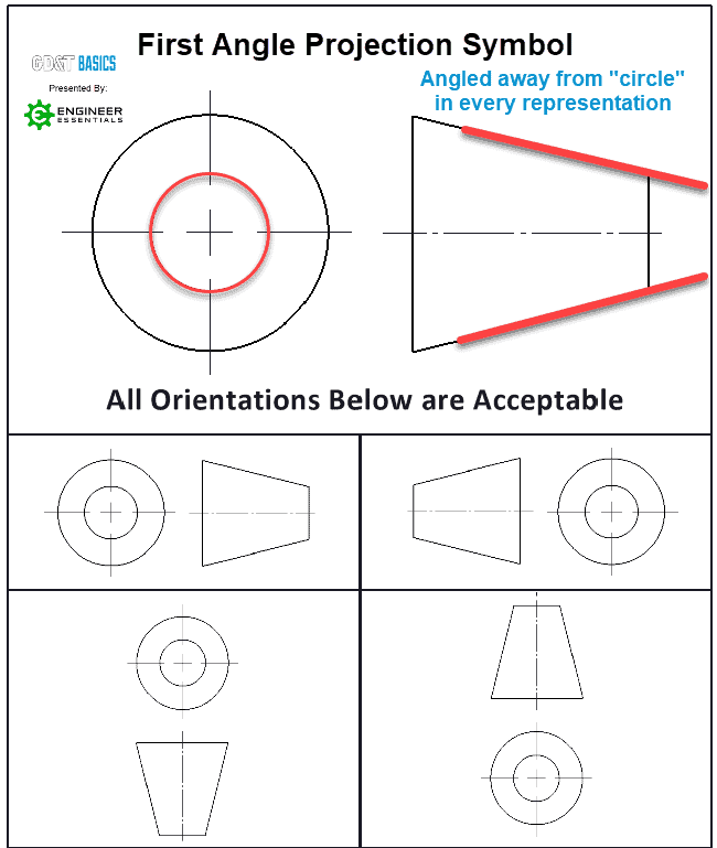
Again there is common confusion about the symbol representation for First Angle Project. There are four ways First Angle Projection can be represented on a print (Figure 4) and all of them are acceptable. The big takeaway here is it does not matter if the “side” view of the “cone” is on the right or left. For First Angle, the “pointy” end of the side view of the cone in the symbol is always pointing away from the front/”circle” as shown in Figure 4 below. All four of these are perfectly acceptable for First Angle.


First-ANGLE-PROJECTION-SYMBOL-PLUG-SYMBOL-ALL-ORIENTATIONS-2.png


from First vs Third Angle – Orthographic Views | GD&T Basics

regards
Nikhil
 
Difference between First Angle Projection and Third Angle Projection :

SR.NOFirst Angle ProjectionThird Angle Projection
1The object is placed in the first quadrant.The object is placed in the third quadrant.
2The object is placed between the plane of projection and observer.The plane of projection is placed between the object and observer.
3The plane of projection is opaque.The plane of projection is transparent.
4Front view is at the top of the horizontal axis.Front view at the bottom of the horizontal axis.
5Top view at the bottom of the horizontal axis.Top view at the top of horizontal axis.
6Right view is at the left side of vertical axis.Right view is at the right side of vertical axis.
7Left view is at the right side of vertical axis.Left view is at the left side of vertical axis.
8It is widely used in Europe, India, Canada.It is widely used in United State and Australia.
 
Here is a simple example of why knowing the projection used is helpful. With no hidden detail which side are these blind holes drilled in?

blind.JPG
 
So I guess I have worked around using these symbols just by declaring "left side view", "right side view", "top view", "bottom view", "front view", and "back view", and isometric views from various directions.

And I use sections, which have arrows for the direction of view.

So it is like an arrow on a section line then, indicating you are looking in the direction of the arrow.

Well I guess ignorance is bliss because these symbols are news to me; never noticed or used them.

Thanks everyone for the feedback.

.
 
Here is a simple example of why knowing the projection used is helpful. With no hidden detail which side are these blind holes drilled in?

View attachment 153264

And so I would assume the holes are drilled in the right side, since they are shown on the right side, but I guess that is a matter of interpretation.

I have never had much trouble figuring out drawings without being aware of the symbols, so I am not sure I would even use them even if I noticed them.

I learn something new every day.

.
 
Here is another diagram I found (not my diagram).

I must admit this is totally foreign to me, and is not something obvious to me at all.
I am having to think about what this really means.
LOL, I probably should know this by this point in my life.

This is totally non-intuitive to me.

Edit:
What is clear to me though is that I have always used 1st angle projection on everything, or as I mentioned, "left side view", "right side view", "top view", "bottom view", "front view", and "back view", but always folded out in 1st angle projection, ie: plan below the front elevation, etc.

With the advent of 3D modeling, it is easy to toss in one or more isometrics in various directions, and that is quite helpful, and very intuitive visually.

I guess it is sort of like me not fully defining my 3D sketches/models.
Never have, not intentionally anyway; I just 3D model away in blissful ignorance, and no problems have occurred.


.
763.jpg
 
Last edited:
So it seems like 1st angle projection means project down and left,
and 3rd angle projection means project up and right ?

I am oversimplifying it ?

Why not just declare front, back, left, right, top, bottom under each diagram?
That is what I do, and just fan everything out from a cube, with the cube rotated back for the bottom view, and the cube rotated forward for the top view.

I can't see declaring an entire sheet as either 1st or 3rd angle projection.

.
 
When I was learning to draw, with pencil on paper, our teacher told us an easy little visual way to tell them apart.
First angle is when the object ( in this symbol) appears to be flipped on its side as if you pushed it over onto that side.
Third angle is when the object appears to be swung into place.
As a European I prefer First angle since that was our way we learned. But you get used to both if you had to.
Fortunately as a 3d modeler I don't have to pay attention anymore :D
 
So it seems like 1st angle projection means project down and left,
and 3rd angle projection means project up and right ?

I am oversimplifying it ?

Why not just declare front, back, left, right, top, bottom under each diagram?
That is what I do, and just fan everything out from a cube, with the cube rotated back for the bottom view, and the cube rotated forward for the top view.

I can't see declaring an entire sheet as either 1st or 3rd angle projection.

.
As always the industry has to declare a standard. Since they declared differently in different parts of the world we have different standards. It is simply to make everybody do it the same way and always the same way. It does not mean there are better or easier ways, or that your way is wrong. It simply means that if a company is going to spend millions on a project that will be completed using 12 different consultants and 125 different engineers, everybody can rely without thinking about it on each other's drawings to be the same.
Remember the Mars lander mission that managed to "miss" an entire planet the size of Mars? It was done by USA and UK engineers who had to comply with each other. Somewhere this failed and probably some drawing was in inches while another was in mm or something like that.
But it could also have been that one drawing from the English was in first angle while the Americans were in 3rd angle.
Standards are designed to prevent these from happening but as we all know even the standards have to be checked.
 
The main thing is to be consistant across a set of drawing. Don't go placing an elevatiion on the left just because it misses the title block if on all the other parts you have been placing it on the right.

I don't know how your CAD deals with it Pat but Alibre allows me to set 1st or 3rd angle as a default and will then place the various views accordingly. I can choose which view of six would be the two concentric circles on the symbol and then whatever other views I choose to use they will be laid out using the projection chosen.
 
Solidworks allows you to drop a part on the sheet, and depending on how it lands, then you can pull a projected view left, right, up, down, or at any one of four 45 degree angles for isometrics.

If you don't get exactly what you want, you can project off of the side of a projected view, but I seldom use that feature.

So I always use top, bottom, left, right, and one or more osometrics, and label each view as such.
Perhaps that is why some drawings confuse me; they don't have the left,right,bottom,top labels.

Once you have looked at a certain number of drawings though, it really does not matter how it is drawn, one can figure it out just by observation, especially if a few isometrics are included.

.
 
I start an engine design in 2D, and then tranfer sketches to 3D.
Sometimes I just draw a simple sketch in 3D.

I find that Solidworks is difficult to sketch in compared to Autocad.

As I get an assembly created, I generally create a 2D set, and put that back in Autocad, as a visual reference, such as below.

And I create one set of images in wireframe with no hidden lines, and another showing hidden lines.

But it always starts with the central image, with views radiating outwards up, down, left, right, and then isometrics.

So below, 8 projections of the central image, on the images that do not show hidden lines.

Eventually this gets done on a per-part basis, with dimensions added.

.
Image31.jpg
 
I was telling Jason that when I was in school, you had the Hewlett Packard calculator folks, and the non-Hewlett Packard folks.

It was akin to the Hatfield-McCoy situation, but with less violence.

I distinctly remember the two groups castigating each other daily about who had a "REAL" calculator.

I was in the non-HP group.
I could never catch onto the backwards notation, and that is how I perceive 3rd angle projection, now that I am aware of it, and since I am not use to it, never having used it.

For the record, Casio calculators RULE !...................HP calculators drool !
I still have the two original Casio calculators that got me through school, and last time I checked, they still worked perfectly.

.
 
I have a nasty habit of working in 3rd angle but still using 1st angle for the plan view (which is a hangover from woodwork drawing in high school).

So my first rule is the drawing must be comprehensible regardless - like the question above "which side are the holes in ?" should not arise - the designer might just be an idiot like me - so relying on a good judgement call by the manufacturer / toolmaker is just bad practice.

Assumption is the mother of all ........

Like this example - one of mine........symbol and notation 3rd Angle Projection - but the plan is first angle - view from above....

A laser cut and bent part....
3rdAngle.jpg


So I added a 3D image to ensure clarity and references to other available files for clarity.

Guess what ? They still bent them all the wrong way. Argued that it was correct to the plan view as 3rd angle. Arguing that one of four views was correct enough to ignore the other three was in my opinion fatuous enough for a firing - but yes the drawing is faulty and if unsure they should have asked the designer or looked at the other files.

It just shows you can't idiot proof everything - but you should try.

Regards, Ken I
 
I could never catch onto the backwards notation, and that is how I perceive 3rd angle projection, now that I am aware of it, and since I am not use to it, never having used it.


.
Unusual as the US and Canada tend to use 3rd angle while Europe and the UK use 1st angle. It is something I have to adjust to when working with US sourced drawings and casting kits. Ignitors and Cams can be the most confusing.

You could also save a lot of time not having to label every view if it is top, bottom, L or R
 

Latest posts

Back
Top