1/2 scale advance-rumley 60-20 traction engine

Home Model Engine Machinist Forum

Help Support Home Model Engine Machinist Forum:

This site may earn a commission from merchant affiliate links, including eBay, Amazon, and others.

hammers-n-nails

Well-Known Member
Joined
Mar 22, 2009
Messages
206
Reaction score
0
well boys here is the begining of our next project, the title says it all. this engine is going to be a copy of and engine that my dads uncle, my great uncle, has had for many years. im sorry i dont have a very good picture of the original ill try to remember to get one next time i go over there. some of the general specs for the model are overall length about 8feet, boiler shell 15'' diameter 30-35 sqft heating surface, rear wheels 32.5'' dia, cylinder size 4.5"diax5"stroke, approximate weight 3000-3500lbs, estimated top speed 1.2mph.

right now dads welding up the boiler and im working on the front axle and pedistal

heres the pics and comments

100_0433.jpg


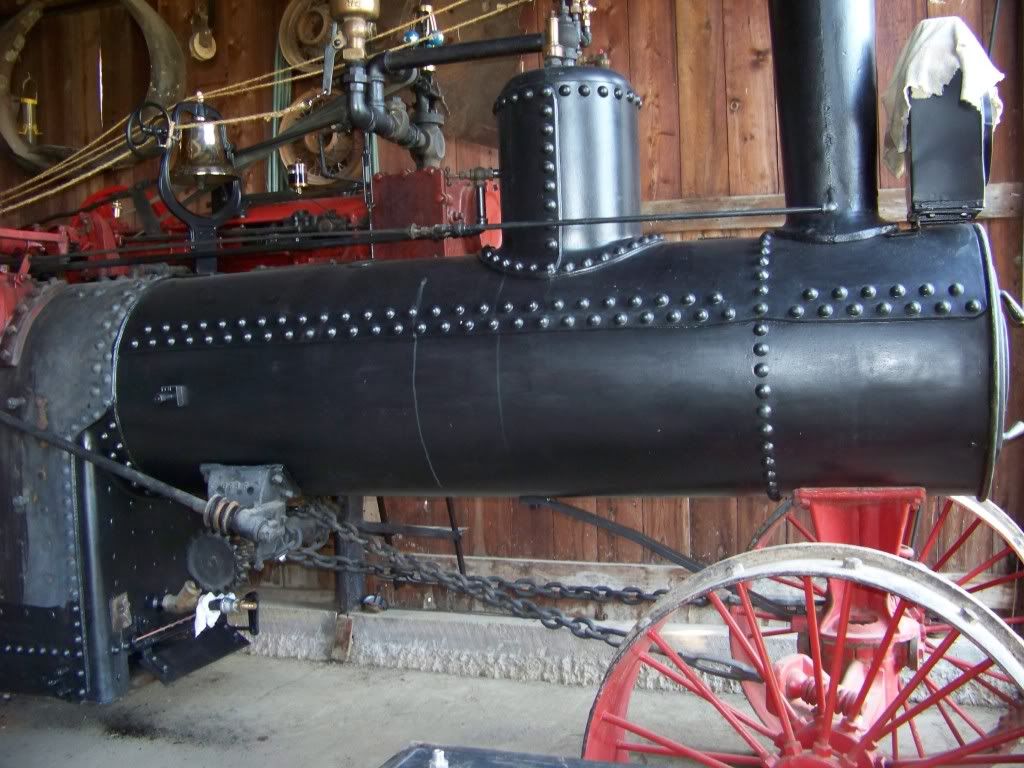
best pic i have of the original

100_0436.jpg


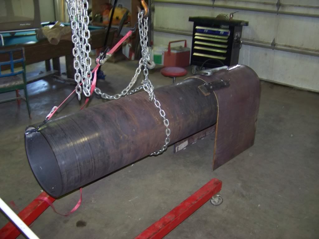
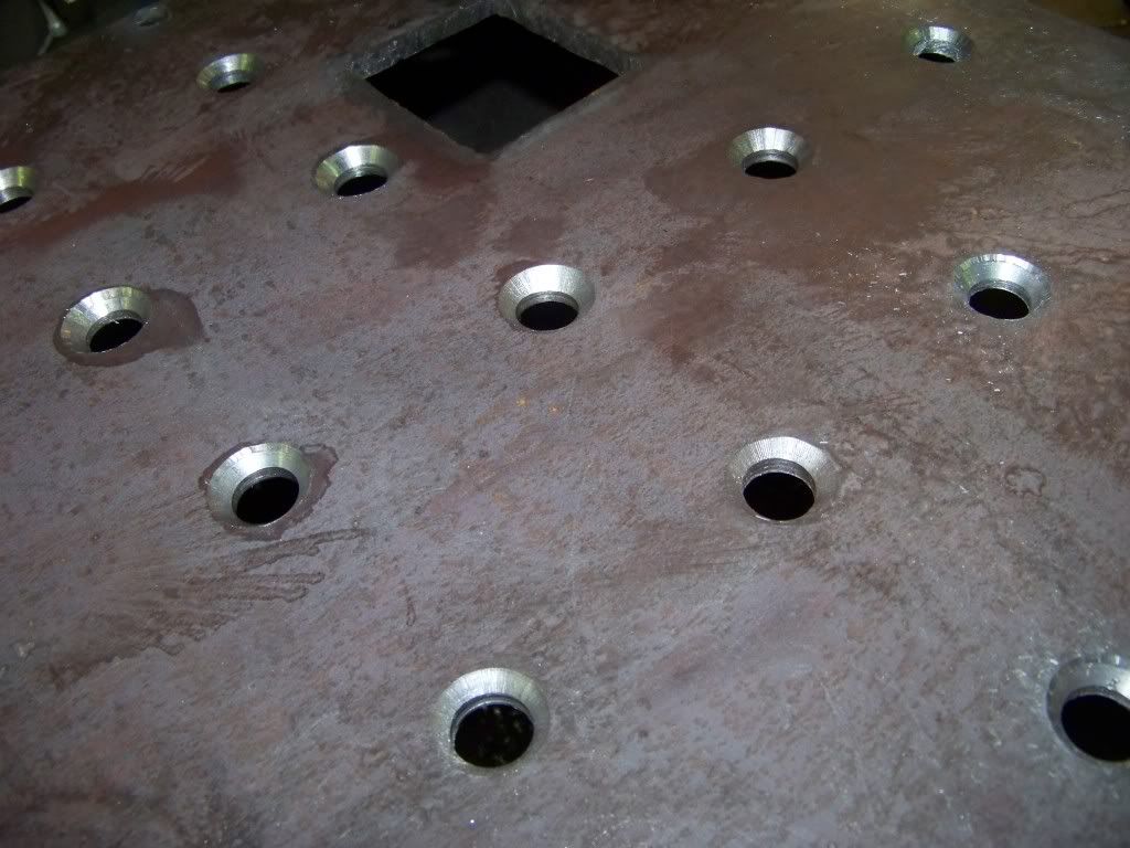
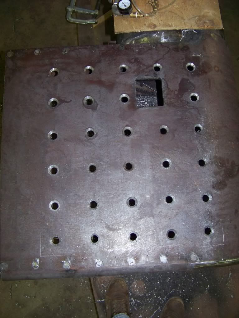
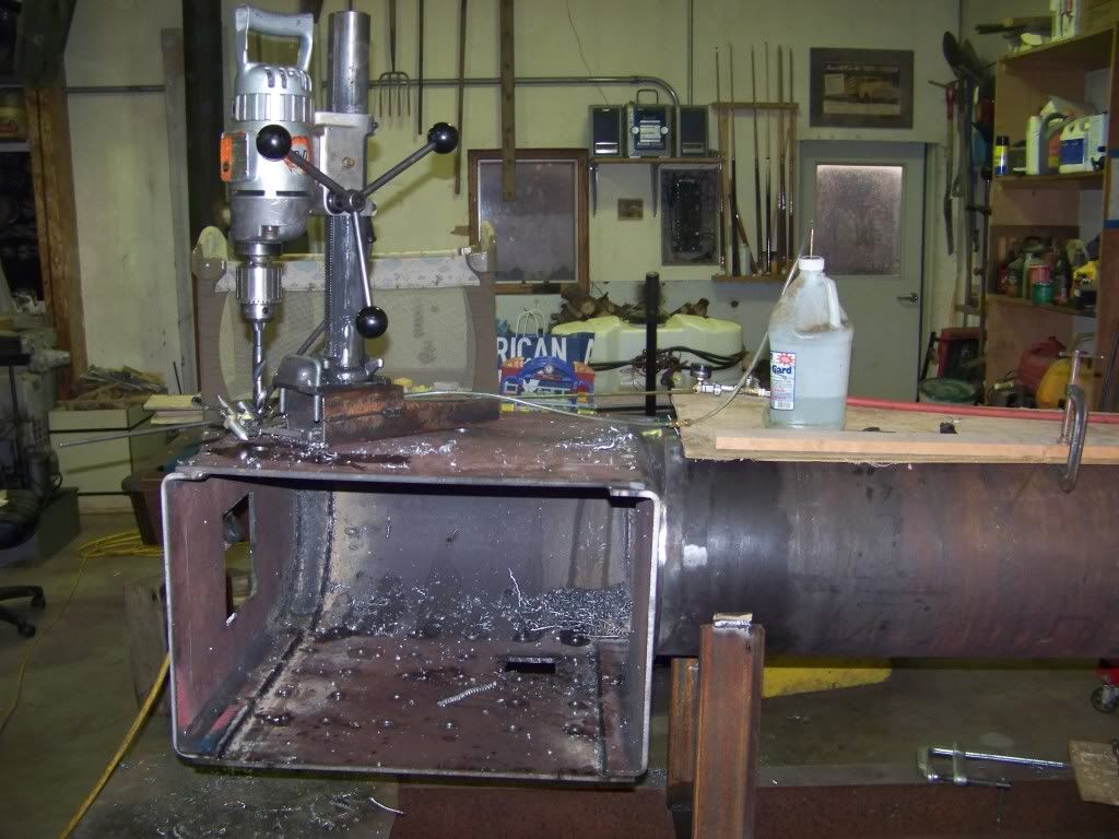
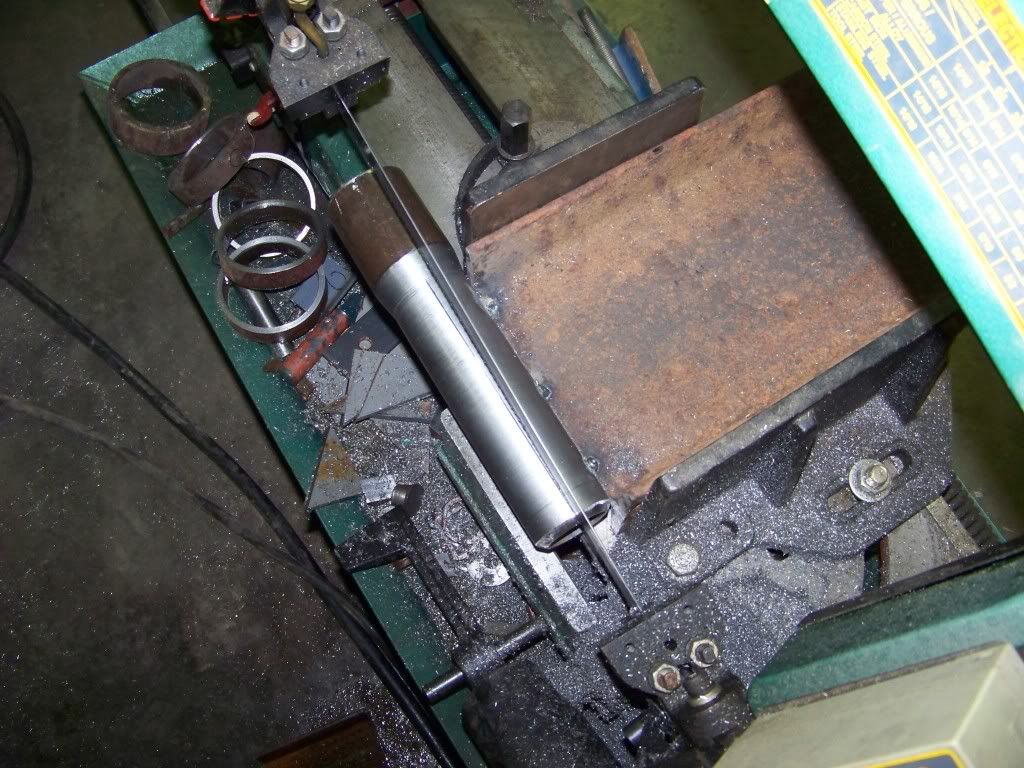
the boiler mocked-up

100_0511.jpg


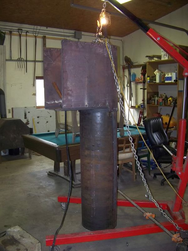
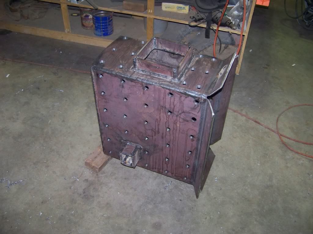
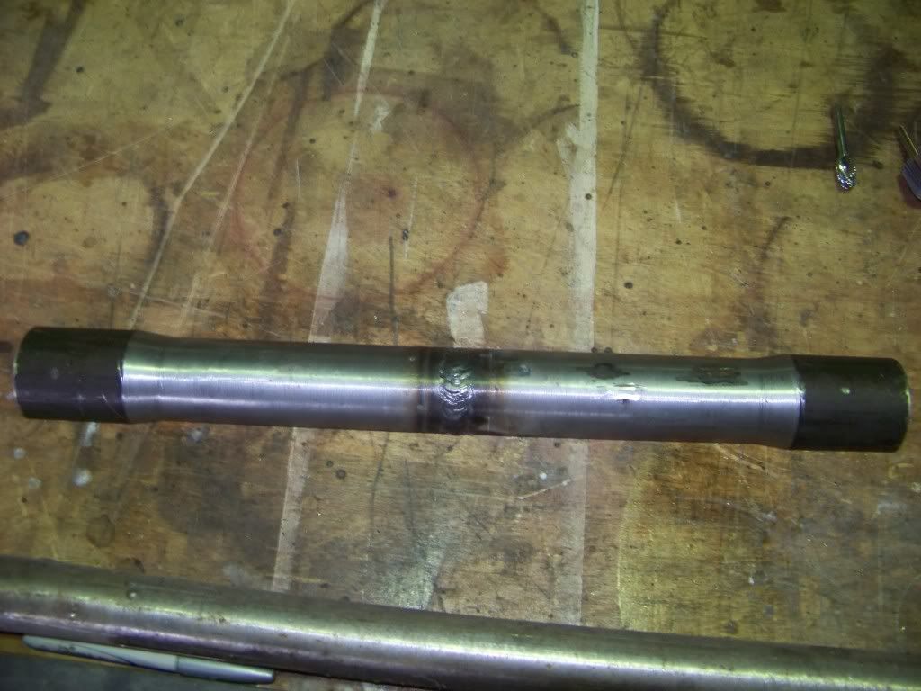
the boiler partially assembled. we whent for a lapped seam boiler for astetic purposes, it will take a considerably longer time to build though

100_0526.jpg


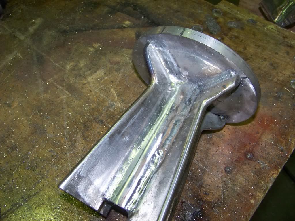
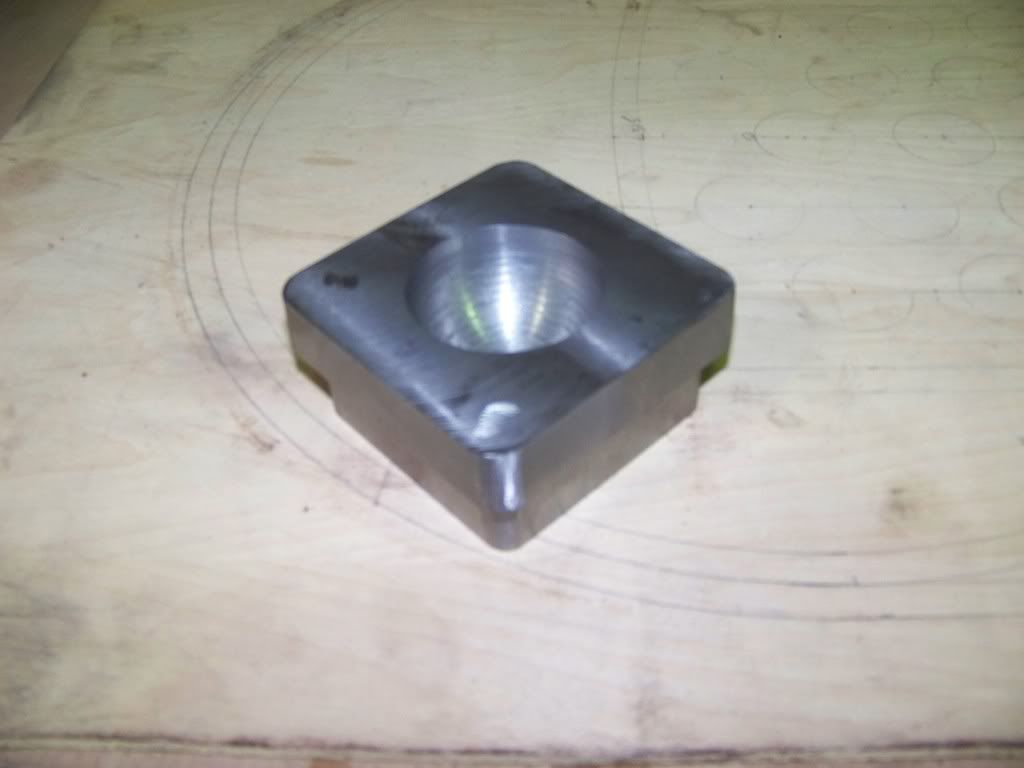
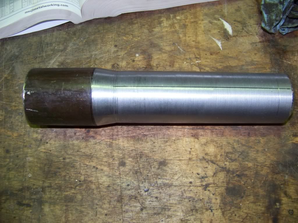
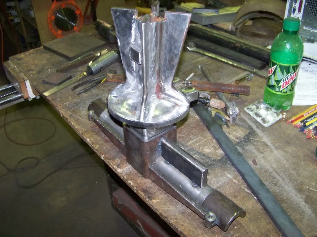
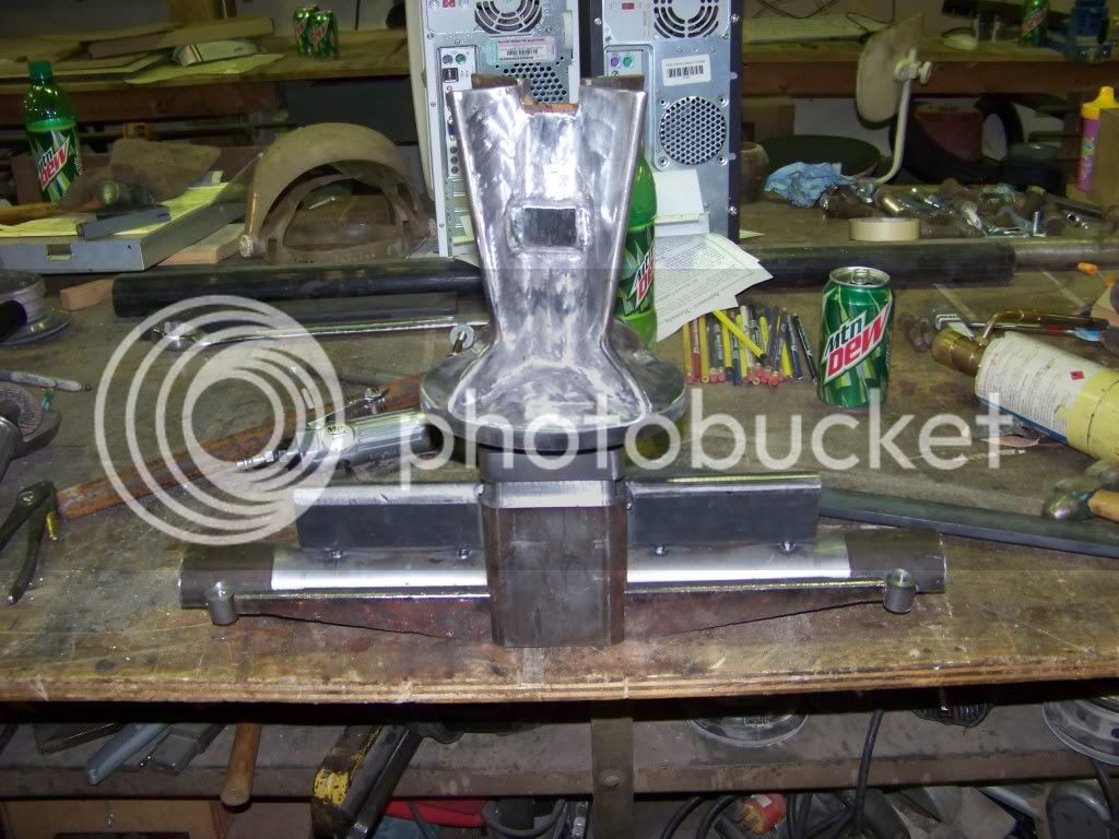
my progress on the pedistal, sorry i didnt get a pic of the pieces before i welded them together, on the end you cant see is a ball that will rest in a socket in the axle to allow it to pivot and tilt side-to-side, i cheated a little bit and used a 2" trailer towing ball. there isnt anything in the pic for scale but the overall length is about 8" and the disk at the bottom is 6 1/2" dia

im having a problem with it and that is that i would like to have a nice 1/4" or so radius where the gussets meet the center pipe, they are welded together obviously and i cant get the die grinder to give a smooth enough finish to satisfy me and the flap disk on the angle grinder cant reach most of it so i was wondering if any of you had any trick ways to accomplish this, i have a cylindrical flap drum for the die grinder but its 1"dia (the smallest i can find) is too big so that doesnt work. any ideas would be great.

100_0437.jpg


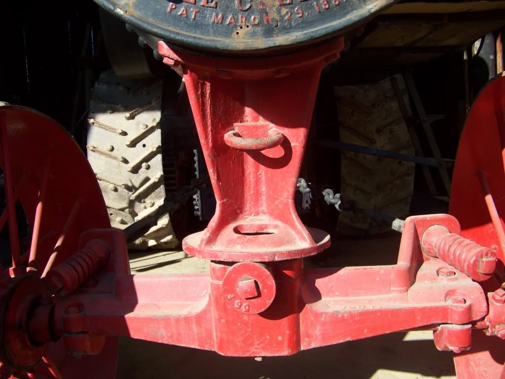
the pedistall and front axle on the original
 
Now that is an impressive project!
Do you have a plan in place for pressure testing the boiler?

Rick
 
Wait a minute! I thought this forum was about 'model engineering'. ;D
No complaint here! I'll look at anything that is steam and/or moves.

1.2 mph! I'd like to see the snail that can't beat that! Uh..wait..that's not right...

Cool. It's just fascinating to see these things. Thanks.


Hi Hammers-N-Nails - Did I get this right? 8 feet long and the boiler lifted with a hydraulic block-and-tackle and this is still called a MODEL ???????????? Give me a break!!!! You will have to put a truck wheel beside each parts photo for size comparison. - Just kidding. I happen to love Rumley tractors. Good luck with your project. I will be following you.
 
H/N, you could use a conical stone in a Dremel or die grinder to achieve the radius you are after. It will take a while and several stones (no pun intended) but the end results will be closer to the appearance you are seeking.

Jim B.
 
Man, that looks like a lot of work! Gonna be a beauty.

Chuck
 
I don't mean to be picky BUT this is model engineering since its 6" scale. As a UK member do you have to have coded welders in the USA for pressure vessel?

MM
 
yeah rick my uncle loaned us a high pressure hand pump to do a hydro test with he said he had taken it up to 300psi on his engine so that would give me a factor of saftey of 2:1 which seems to be pretty standard wouldnt you say?. and to answer your question mickey the answer is it depends on the state i happen to live in missouri where coded boiler isnt required or even a state inspection for non-commercial boilers that you build yourself, the only other state i might go to is iowa and there laws are pretty much the same as near as i can tell.
jim i thought of that but didnt try it because i didnt think the stones would last anytime or work that well but earlier today i got one and tried it and it worked fine after i roughed it in with a burr.
 
Over here when calculating boiler designs you work with something like a factor of 5:1 and then test to twice working pressure. We would also not use the type of firebox construction you have, it would be all welded and dummy hornplates attached, and definately not the lapped barrel.

What calculations have you done to etablish plate thickness etc? Have you allowed for the temperature when calculating? What allowance for wasting of the steel? etc

Do you have to get the boiler tested for insurance perposes like we do if we want to ru in public?

Jason
 
this exact type of boiler has been built a million times obviosly so there are generally accepted standards that have proven reliable. the main thing is that you use 3/8" a516? boiler plate and a 3/4"dia stay bolts are 4" on center. thats what everybody else does and as far as i know noone has ever had any problems. the show with the strictest standards that i plan to go to gives a visual inspection and performes a hydo test and your good to go. as far as allowing for metal thinning this engine is probably only going to have water in it 1-2times per year so when you compare that with a farm tractor from the 1910's that was in continuous operation getting filled up with pond water, irregular cleaning, etc i figure my grandkids will be dead before it has rusted enough to leak. also this boiler, while it is lap seamed and will have rivet heads on it, the structual joints are all welded just as they would be in any other type of construction, that was just done to make it original looking. i am curios to the objection to using a lapped boiler, why is that?
 
Even in the larger scales our boiler barrels tend to be made from seamless tube. I'm not 100% sure if there is a specific ruling on lapped joints but I've never seen one used on a model boiler.

Your 3/8 plate for all parts of the boiler also seems a bit on the thin side, A quick calculation using the formula in one of my Model Traction engine books would give 1/2" plate for a 15" barrel with working pressure of 120psi (5/8" for 150psi)and the stay spacing for 3/8" plate works out at 2 1/2".

3/4" dia stays are OK for 3/8" plate but 1" would be used if following the results of the above calculations.

These figures are seem about right as a 6" Garret engine which also has a 15" barrel would have the barrel, wrapper and firebox in 1/2" plate and the tubeplate and front & rear firebox plates in 5/8" material.

All tube and plate must be the correct spec for boilerwork and accompanied by the paperwork to pruve it.

If you are interested here is a build diry of a 6" garret that shows quite a bit of what goes into a boiler to meet our regulations and some interesting machine setups to deal with some of the larger parts.

Jason

BTW the next model I want to do is a 2" engine and that has 5 gauge (0.212") plate
 
i what book do you have on model traction engines? would you reccomend it? i did some calculations after posting yesterday using formulas from the book "steam boilers their theory and design" by HB Parsons and came up with a working pressure of 243 psi working pressure for the barrel assuming a joint strength of 50% burst strength of 1500psi though a welded joint should be 100% and a working pressure of 250psi for 3/8 plate with a stay pitch of 4", also shouldnt a 3/4" stay with tensil strength of 60,000 psi have an ultimate strength of 26,500lbs where the working pressure of 150psi x 32sqin=4800lbs, giving a factor of saftey of 5.5?
 
I took the formula from "Introducing Model Traction Engine Construction" by John Haining who has at least 10 model engine designs to his name, it mostly deals with 2" so may not be that relevant to what you are working on. There is just one chapter on boilers but the author does have a more detailed manual on boilers.

The book I find best for TE Construction is this one which deals with 3"-6".

I posted a link to this thread on what is probably the most active Model Traction Engine site when you first posted your progress as I thought people would be interested, there are a few comments hereon the boiler if you are interested. general oppinion is that it will be OK for 150psi but most would like a bit thicker plate and no lapped joint.

Jason
 
its been awhile so heres some new pics on what little visible progress has been made. the boiler just takes a long time, hes about got all the holes for the stays drilled. ive not got much to show, looking at pictures and sketches and trying to make something that looks exactally the same takes along time, some say im a perfectionist and that isnt helping helping my production any.

pics with comments below

100_0551.jpg


100_0550.jpg


100_0552.jpg


100_0553.jpg


the magnetic base for the drill press burnt up so he built a channel iron base with a slot for a bolt to go through one of the stay holes until he can get a new base or fix the old one.

100_0529.jpg


the socket for the ball on the bottom of the pedistal to rest in on the rotary table ready to be cut. i cant figure out how to cut an XZ arc with the dro so i switch the Y and Z cords, it works.

100_0530.jpg


the finished product it will fit partly inside a 3 1/2" X 3 1/2" X 1/4" square tube

100_0534.jpg


part of the axle support after turning, the taper serves no function but thats how the original is so thats how i built it.

100_0535.jpg


spliting it in the bandsaw, its tack welded to that piece of i beam, it worked suprisingly well

100_0536.jpg


after splitting and welding back together of course

100_0555.jpg


100_0554.jpg


100_0437.jpg


my work so far and the original again for comparison, the socket block is just sitting there it will be pressed in when im satisfied with the rest


It looks like you got a lot done to me! This is quite an undertaking.
The boiler pedestal/steering block is looking good!

Dean
 
Its comming along, can I ask what the small square hole in the side of the firebox is for?

Jason
 
the wood/coal boilers could be converted to burn straw, in a straw boiler there is a plate that starts at the lower part of the flue sheet and slopes upwards towards the back about 2/3-3/4 the length of the firebox so the gases had to travel farther from the fire until they entered the flues so that all the chaff and embers would be burned up before they got to the flues. in a dedicated straw boiler the plate is another waterleg, im not sure how a conversion was done. so that door is there so you can clean the top of that plate off. other than that i dont know that it really serves any pourpose, its just one more detail we decided to add, the old man says its a PITA to build so it probably wasnt really worth doing since it serves no function to us. do you not have straw burners over there?
ill try to get a pic of the page on straw boilers for you if you want.
 
Most of our makers did the option of straw burners for the export market when their was a British Empire, as far as I know the straw burners were not used on the domestic market and very few woodburners.

The straw burners had some form of feeded that pushed the straw into the firebox, from their I don't know what went on inside.

Jason
 
Back
Top