Metal Mickey
Well-Known Member
- Joined
- Jul 5, 2008
- Messages
- 612
- Reaction score
- 6
I didn't know whether a steam traction engine in 2" scale was relevant to this forum. However I see there is another Fowler in build so I will share this build with you....It will not be completed soon. In fact another couple of years minimum is my expectation.
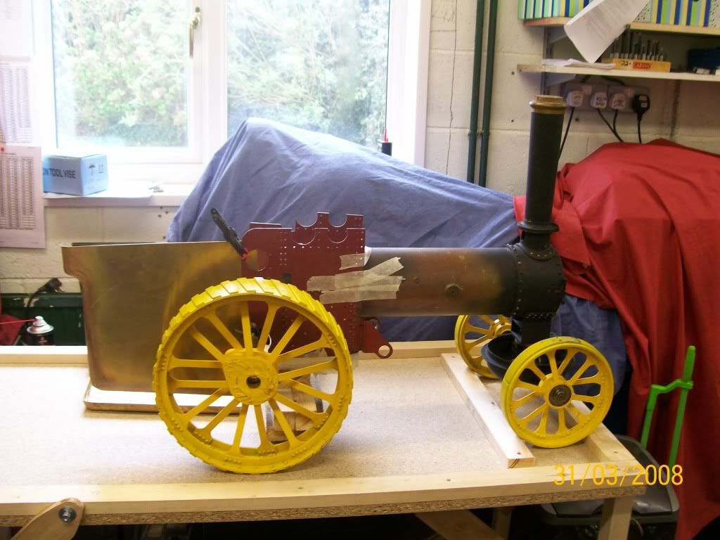
To give some sort of idea of what it looks like the picture below will give a guide, although the picture shows it loosely trial assembled.........
I bought the Fowler as an unfinished project whilst I was still in work some 6 or 7 years ago. However my workshop and model engineering has only been running for some 12 months or so and most of that time taken up with other projects (mainly a Mills diesel 1.3cc aero engine).
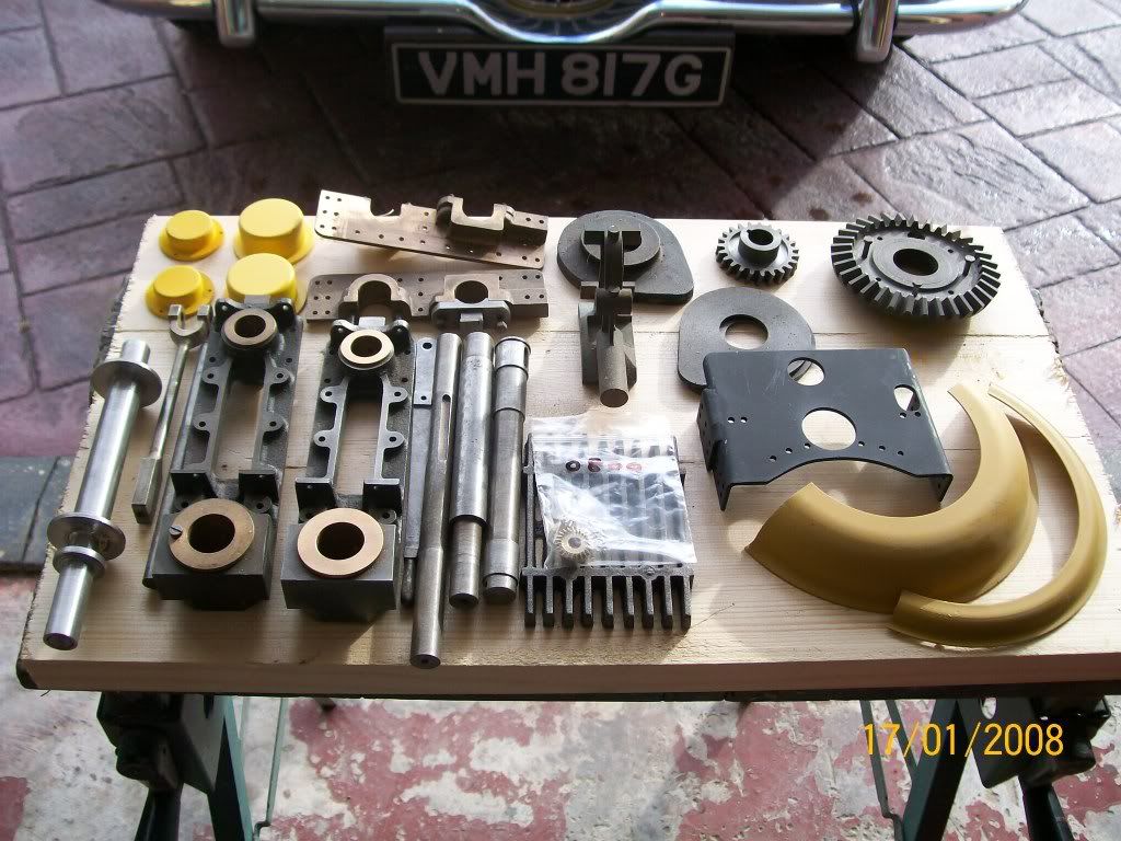
The gentleman I bought the set of castings and boiler from had bought a full set of gears and a commercial boiler plus he had the wheels built professionally. So I take no credit for them. There were a set of hornplates completed but I re did this work. I also built all the steering work and some other small items.
A picture of some of the items that came with the purchase of the unfinished project.......
After finishing the Mills recently, I can say that only since that time (just a couple of weeks really) have I truly started work on her. So it may be relevant to list here here now.
The first thing I did was to review all the plans (which are nicely yellowed now!). I have trial fitted many items in the past to familiarise myself with the model and gone through the manual to see what needs to be done to get the major item correctly fitted, that of the hornplates. These are the plates of steel that are attached to the boiler (which acts as the chassis) an hold all the shafts (gears and crankshaft) and the rear axle, so it has to be correct.
It was in my 'program of works' for 2008 to get the Fowler standing on its own wheels and have the steam chest bolted to the boiler. I doubt very much that that will be achieved now this year but hope to have it standing on its wheels at least.
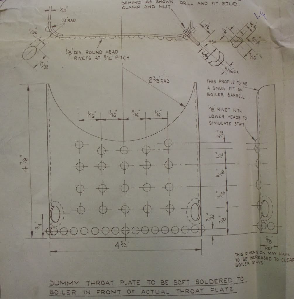
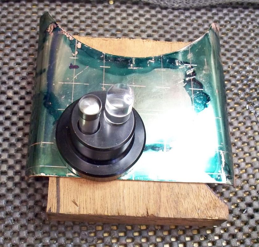
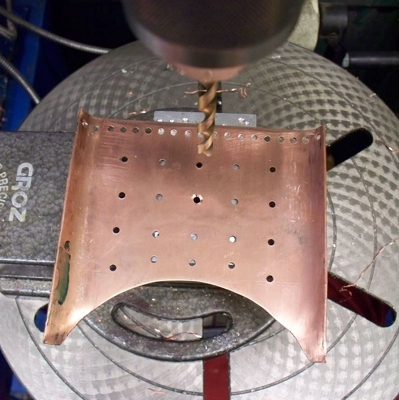
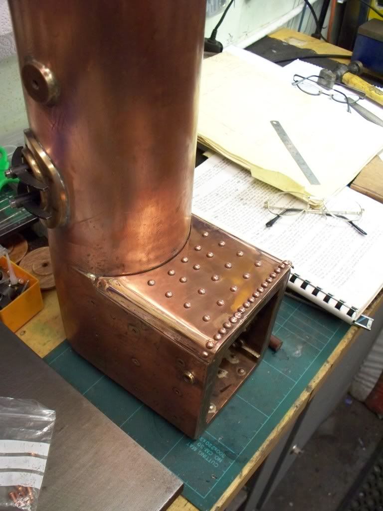
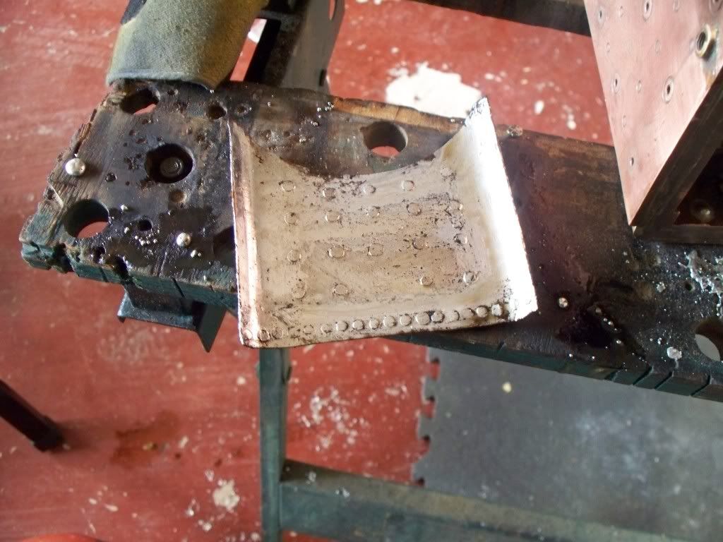
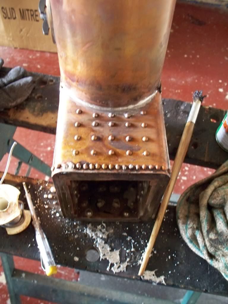
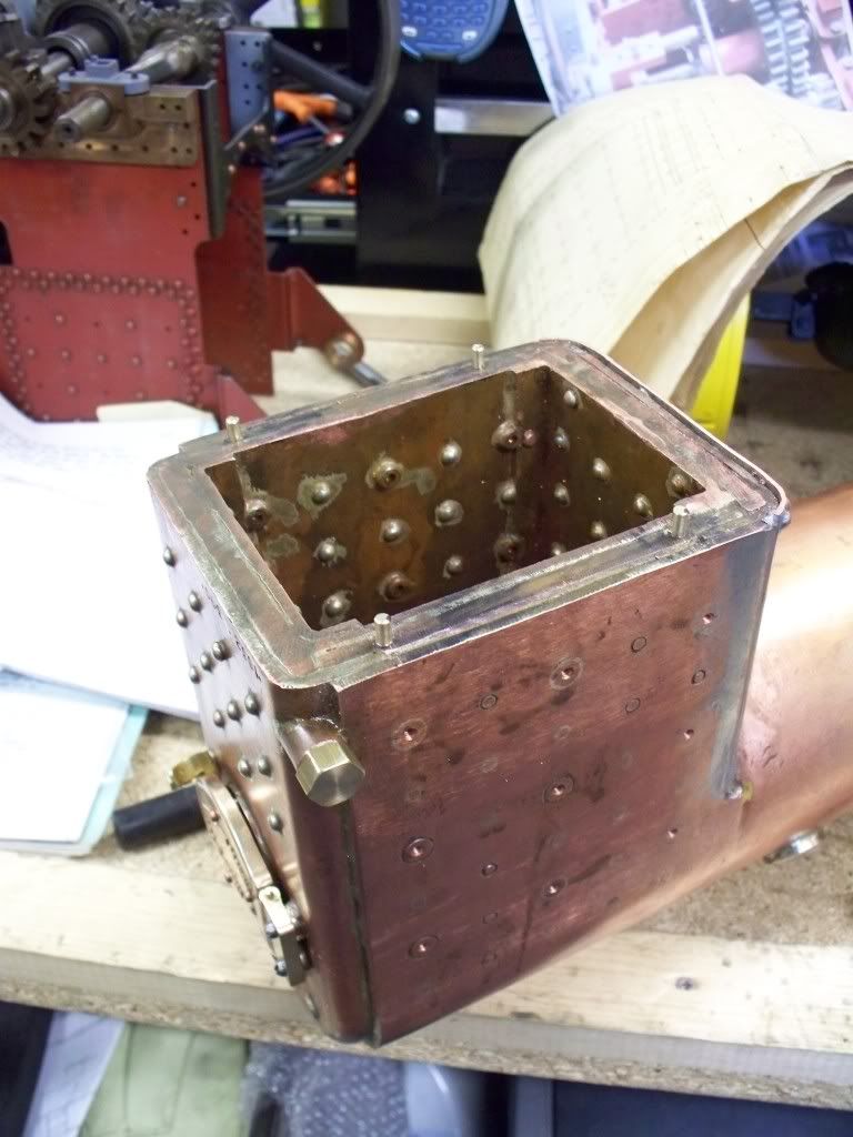
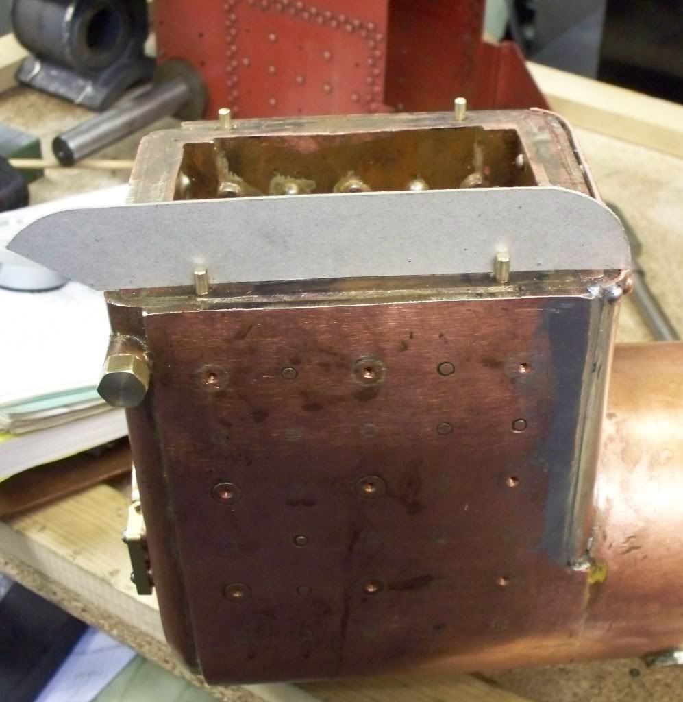
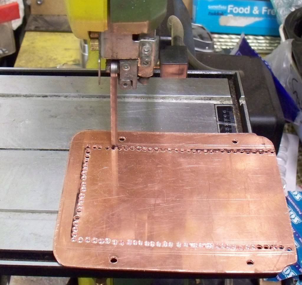
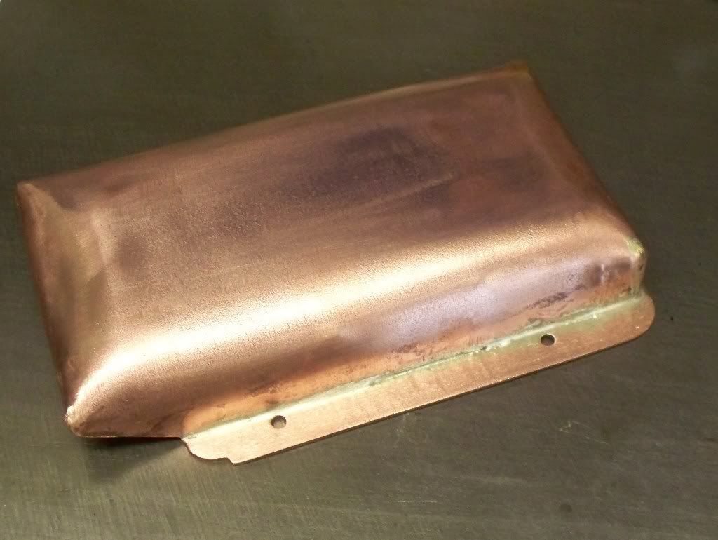
So the tasks started on first was to complete the boiler accessories before attaching the hornplates. In particular this meant fitting the fire door, the dummy front plate and the dummy manhole cover. The dummy manhole and the fire door are nearly completed and full details are carried on my website http://www.mikes-models.com/ccfowlerdiary.html.
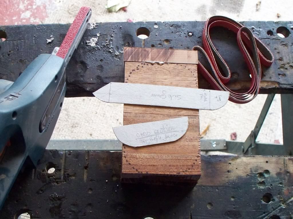
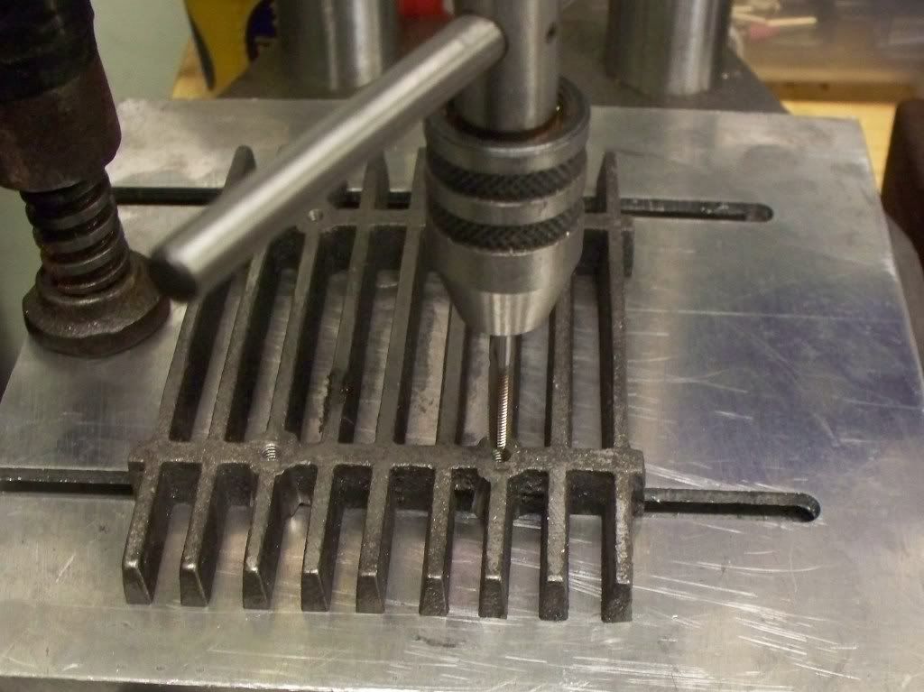
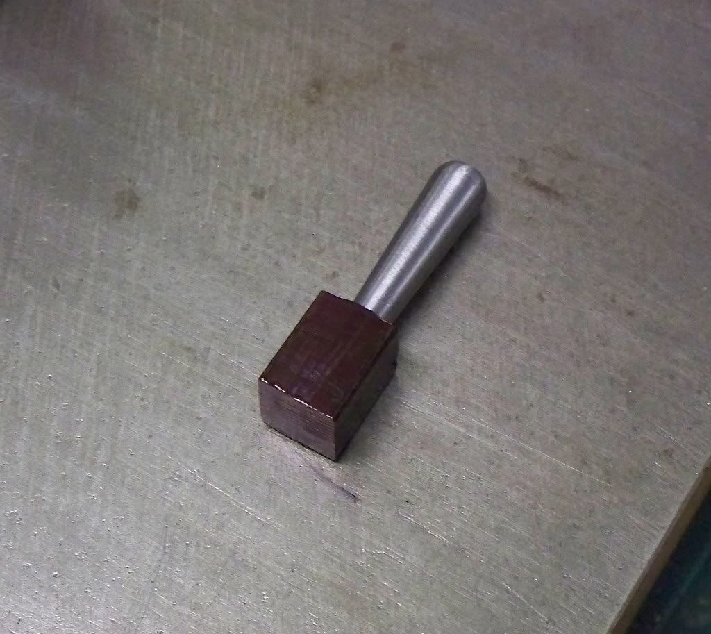
I am finding that there were some items made early on that I feel I can do better ow and these are replaced as and when. One such item is a long lever that is under construction at the moment and part of which is shown below. Whilst it is not required for the boiler and hornplates it has sat there giving me a dirty look for some time, so its the current task.
[imghttp://i353.photobucket.com/albums/r379/brixham-engineer/fowlerleverandfiredoorfin1109200-1.jpg]http://[/img]
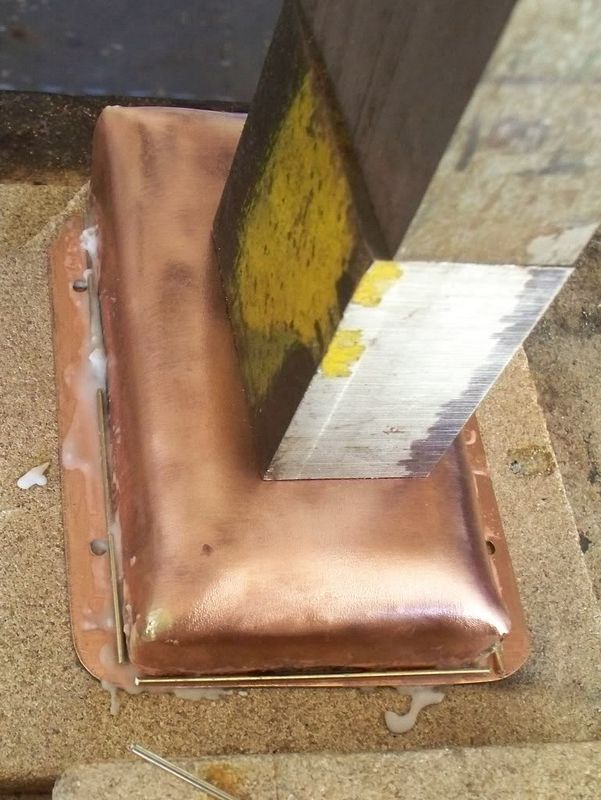
The end of the lever has a handle which I am making separately then silver soldering to the lever body....
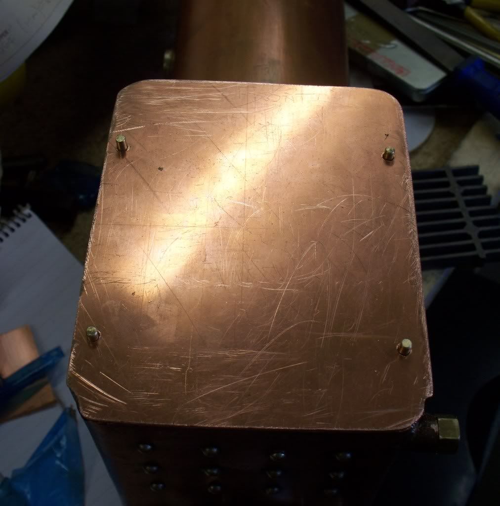
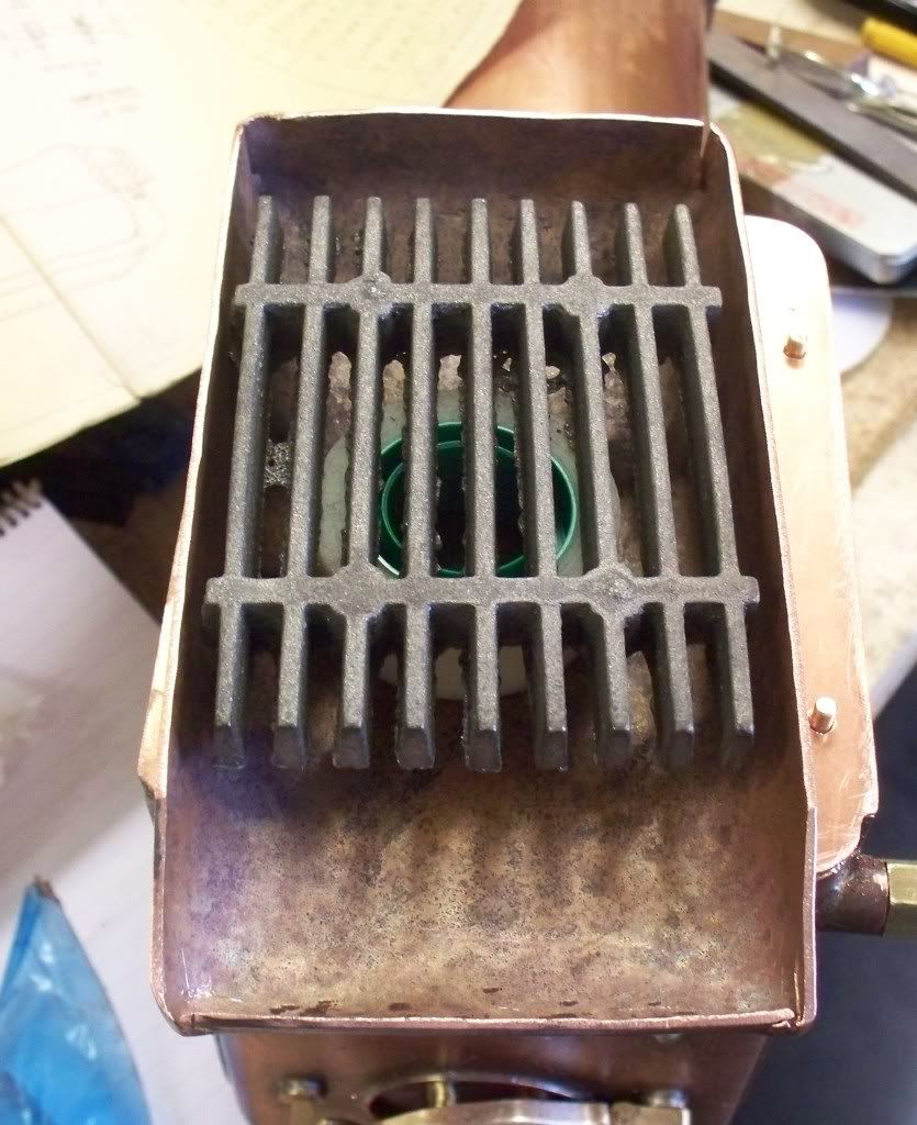
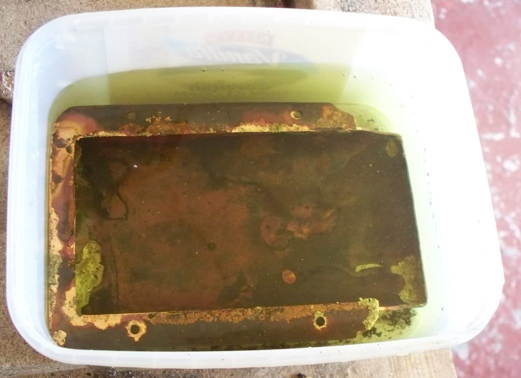
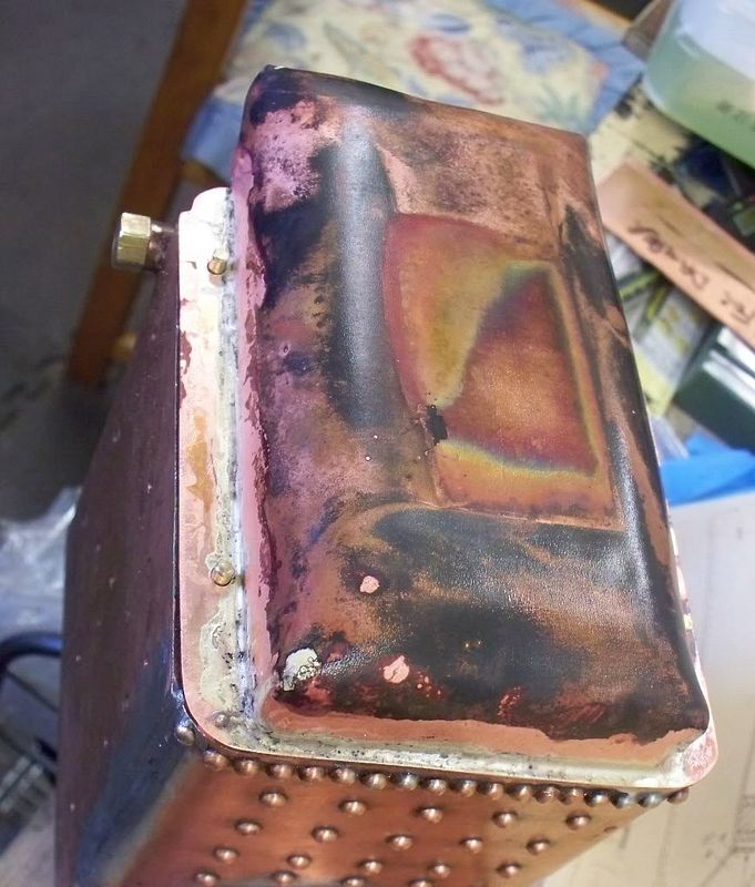
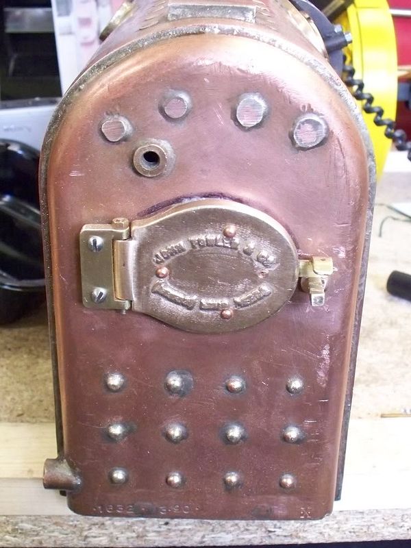
I have been surprised at how long it takes, for what at first look seems 'simple'. One example is the fitting of the fire door below.
Anyway I guess it will get more interesting when it comes to the gearing/crankshaft/steam chest fitting.........One thing is for sure.........it will take some time to complete. And once done, what shall I do with it? Well I won't build a trolley and ride behind it. Not that I have anything against those who do, its just i couldn't get down and up again! Hopefully sometime next year it should be running on air........but then again.........
To give some sort of idea of what it looks like the picture below will give a guide, although the picture shows it loosely trial assembled.........
I bought the Fowler as an unfinished project whilst I was still in work some 6 or 7 years ago. However my workshop and model engineering has only been running for some 12 months or so and most of that time taken up with other projects (mainly a Mills diesel 1.3cc aero engine).
The gentleman I bought the set of castings and boiler from had bought a full set of gears and a commercial boiler plus he had the wheels built professionally. So I take no credit for them. There were a set of hornplates completed but I re did this work. I also built all the steering work and some other small items.
A picture of some of the items that came with the purchase of the unfinished project.......
After finishing the Mills recently, I can say that only since that time (just a couple of weeks really) have I truly started work on her. So it may be relevant to list here here now.
The first thing I did was to review all the plans (which are nicely yellowed now!). I have trial fitted many items in the past to familiarise myself with the model and gone through the manual to see what needs to be done to get the major item correctly fitted, that of the hornplates. These are the plates of steel that are attached to the boiler (which acts as the chassis) an hold all the shafts (gears and crankshaft) and the rear axle, so it has to be correct.
It was in my 'program of works' for 2008 to get the Fowler standing on its own wheels and have the steam chest bolted to the boiler. I doubt very much that that will be achieved now this year but hope to have it standing on its wheels at least.
So the tasks started on first was to complete the boiler accessories before attaching the hornplates. In particular this meant fitting the fire door, the dummy front plate and the dummy manhole cover. The dummy manhole and the fire door are nearly completed and full details are carried on my website http://www.mikes-models.com/ccfowlerdiary.html.
I am finding that there were some items made early on that I feel I can do better ow and these are replaced as and when. One such item is a long lever that is under construction at the moment and part of which is shown below. Whilst it is not required for the boiler and hornplates it has sat there giving me a dirty look for some time, so its the current task.
[imghttp://i353.photobucket.com/albums/r379/brixham-engineer/fowlerleverandfiredoorfin1109200-1.jpg]http://[/img]
The end of the lever has a handle which I am making separately then silver soldering to the lever body....
I have been surprised at how long it takes, for what at first look seems 'simple'. One example is the fitting of the fire door below.
Anyway I guess it will get more interesting when it comes to the gearing/crankshaft/steam chest fitting.........One thing is for sure.........it will take some time to complete. And once done, what shall I do with it? Well I won't build a trolley and ride behind it. Not that I have anything against those who do, its just i couldn't get down and up again! Hopefully sometime next year it should be running on air........but then again.........
 and it sure does belong on here!!!!