Double acting Double Oscillator

Home Model Engine Machinist Forum

Help Support Home Model Engine Machinist Forum:

This site may earn a commission from merchant affiliate links, including eBay, Amazon, and others.
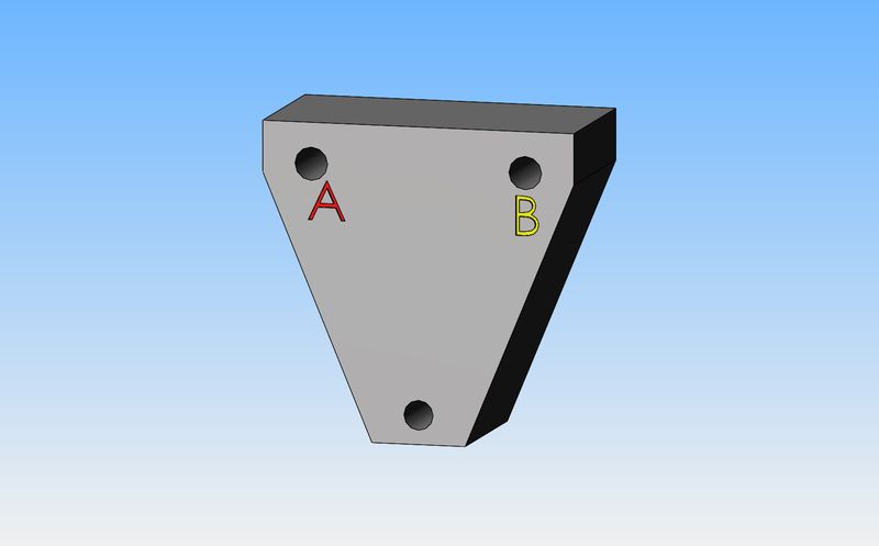
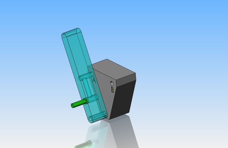
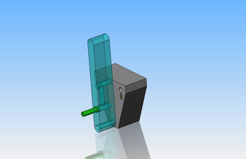
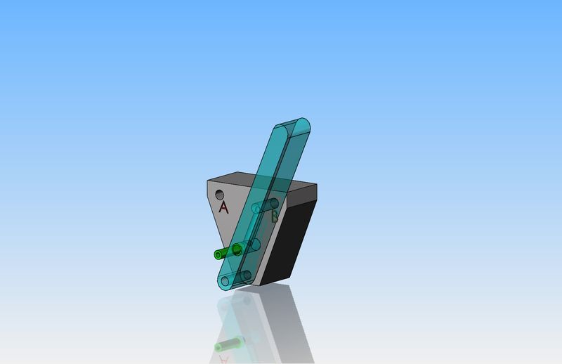
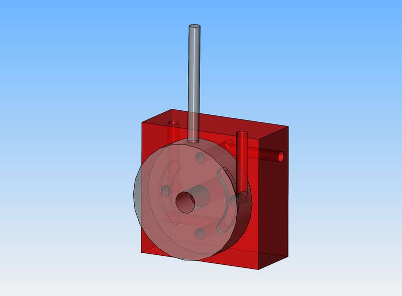
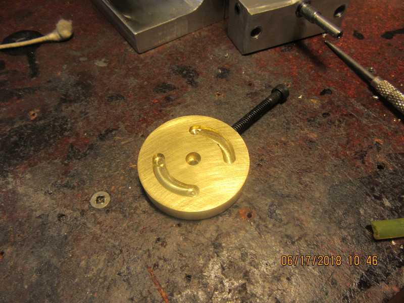
Now we're going to engage in a little foolery here. The part shown is part #1 of a theoretical reversing valve. All you really need to know is that with an oscillating engine, if you put air in port "A" and let the air go thru the engine and come out port "B" the engine will revolve clockwise. However, if you put the air in thru port "B" and let it run thru the engine and out port "A", the engine will revolve counter-clockwise. The third hole with no designation is going to be a pivot for a reversing lever.---Use your imagination---It helps.
rcKmf5.jpg
 
So here we have the reversing lever in position #1. Air flows in the green inlet tube, up thru a passage in the lever, and out a hole in the far side of the lever which is lined up with port "A". Air flows in port "A", thru the engine, and out port "B".---Engine revolves clockwise.
AWDRIA.jpg
 
In this picture, the reversing handle is at mid position. Air flows in thru green tube, up thru passage in handle, but can't flow out far side of handle because it is not lined up with port "A" or port "B'. Engine is stopped.
C0ipxp.jpg
 
In this picture, the reversing lever has been swung over until it lines up with port "B". Air enters thru the green tube, up thru the internal passage in the handle, into port "B", then thru the engine and out port 'A", causing the engine to run counter-clockwise. Remember, that hole at the bottom of the lever is for a "pivot shaft".--There is no air flowing down towards the pivot, ever.
BYp5YB.jpg
 
So---As I said earlier, I have an idea for a reversing valve, but it is crude. Even under the best of conditions it would be difficult to keep air from leaking like crazy, and it is crude having the airline running to the reversing lever. I know it would work.--However---None of this is "new" stuff. I am sure that somewhere over the last 200 years, a far superior and simpler design must have been made. I am looking for that "simpler and superior" design now, and remember, it has to be something simple enough to be fabricated on a manual mill and lathe.---Brian
 
Things have moved along briskly. A fellow in the U.K. sent me a picture of a disc style reversing valve. I have spent the last two hours trying to be Superman with x-ray vision and see whats inside, but I think I have it.
The ports going out to the cylinder are on the extreme right and extreme left on the face of the block. Air coming into the block comes out at the top port on the face of the block. Air exhausting from the block has it's port at the extreme bottom of the face on the block. You would have to swing the handle 45 degrees either way from the vertical position to make the engine run clockwise or counterclockwise.---i think!!!
442Ly9.jpg
 
Excellent job Brian, Only thing I missed hearing was what the pressure was you had it running in the finish? Seemed very low to me and that is always the challenge I think with these engines.
Here is a video of my attempt at Elmer's H Twin I referred to earlier and I apologize in advance for the compressor noise.
I made it at double Elmer's specs and converted to metric on the fly as that's what I work in. One set of tooling, just multiply by 25.4 but don't lose that little fly spec.
John B
 
Last edited:
That now looks even better, Brian. You enjoy it, and I enjoy it. The reversing valve discussion is interesting.

Thank you for responding to my post about power-take-off.

I consider my day to be starting right if I get my cup of Dark Magic coffee and read a post from you.

--ShopShoe
 
Thanks to Raymon in the United Kingdom for sharing his rotary reversing valve design with me. I will probably build this. It only consists of two pieces plus the center pivot and handle.
WATxhG.jpg
 
Last edited:
I had hoped to start on this reversing valve today, but life got in my way. Had to take good wife out to buy a new patio umbrella, which turned into a patio umbrella and two wicker patio chairs. Then had to wash the rear deck before we could put the new chairs on it, then had to dismantle the old patio umbrella-----anyways, you get the idea. I did stop at my metal suppliers and check out a piece of 660 bronze to make the reversing valve out of, but decided that for $42 (which was the asking price) I could use a piece of aluminum I already have for the dark blue part and some brass that I already have for the round reddish colored part. That dark blue piece is 3/4" thick, and has more holes and passages in it than Mamoth Cave. My original plan was to have that round reddish colored piece 3/8" thick, however since I have 1/4" brass plate I may end up soldering two pieces of 1/4" plate together and make it 1/2" thick. I'll figure that part out when I get to it.
FvwwC9.jpg
 
By redesigning the frame, it not only simplifies the construction of the frame pieces, it also gives me a nice vertical surface on which to mount the intake/exhaust manifold.
xjOxqp.jpg

Brian, why not make the central block between the plates the manifold?
 
Brian. Just an idea: instead of porting in the end face of each angle, the central spacer block could have porting in it, making the external pipework tidier - no need for tees & elbows. Could build in a reverse control as well.

Also, I suggest a couple of drill-rod dowels in holes reamed through all three parts to ensure proper alignment of the crank bearings on re-assembly.

Charles
oops, I had the same idea but replied before I saw your note
 
Brian, When you said you wished for x-ray vision but thought you figured it out you are right. Rudy Kouhoupt used the same type of valve back in the 60's on his beam engine. If you look close in the photo you can see the 4 ports on the side of the cylinder. Gary

dd5e57bd8a8150c270bf544116014e5d.jpg
 
Pardon my momentary OT.

adolfgalland,

Can point me to the archive where Rudy K's engine is. It looks like something I would be interested in.

Thank You,

--ShopShoe
 
ShopShoe, The original article was in the December 1961 Popular Science. I have heard that it is listed in John-Tom plans.

Gary
 
Work is progressing on the reversing mechanism. The first plate with all of the passages in it is finished, all except for the area at the top where the blue layout dye is. That will be filed to match the contour of the rotary plate which I hope to make tomorrow. A search of my brass drawer yielded a piece of brass 1/2" thick so at least I'm not going to have to laminate two pieces of 1/4" brass together like I originally thought.
GXt03L.jpg
 
This morning I finished the reversing disc. In the "set up" picture you can quite easily see that the slot on one side was cut with a 4 flute endmill that was duller than a hoe. The other side was cut with a new 2 flute carbide endmill. And of course, the all finished shot. Now I have to go and take two grandchildren to a live play of "Cinderella" at our community theater. I liked the Grimm's fairytale version where the ugly stepsisters cut off their toes with the axe to try and get the slipper on.--Might not set well with todays audience though, I suppose.
cEk2hW.jpg

hsX6ef.jpg
 
Today I successfully completed my first reversing valve. These valves are not difficult to build, but the set-up is a bit fussy so that the valve doesn't have any major air leaks. A gentleman in the United Kingdom was kind enough to send me a picture of a disassembled reversing valve that he had built, and that served as the basis for my design. Thank you, Raymon. The video shows me operating the reversing valve, and I must say, I am very pleased with it.
 
Last edited:
Back
Top