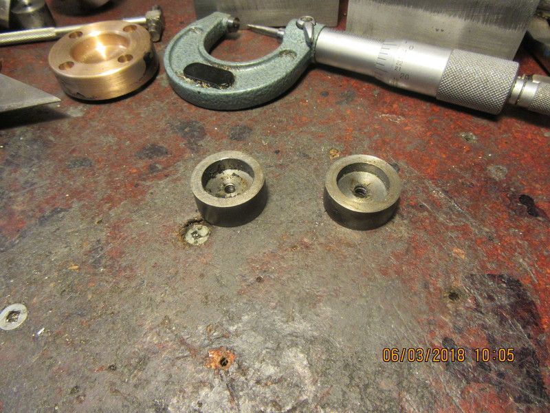
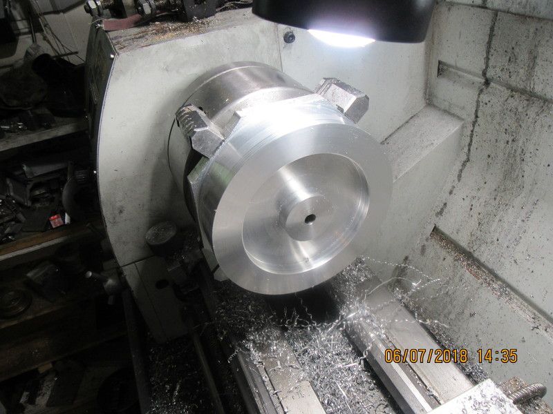
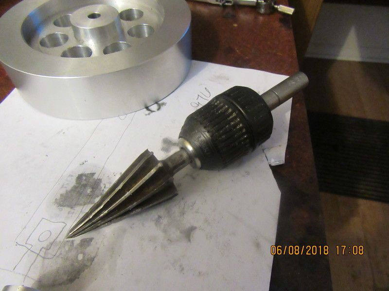
The third test has just been completed. I burned up two drill bits trying to enlarge the center hole in that "grown" piston, to mount it on an arbor. So--not only does the heat and quench make the piston marginally larger, it makes it harder than the devil's horn. Test is over. I conclude that "growing" a cast iron piston is possible, but not advisable because the iron becomes super hard and can no longer be machined with conventional tooling.---Brian