Double acting Double Oscillator

Home Model Engine Machinist Forum

Help Support Home Model Engine Machinist Forum:

This site may earn a commission from merchant affiliate links, including eBay, Amazon, and others.
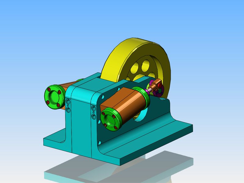
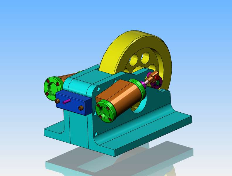
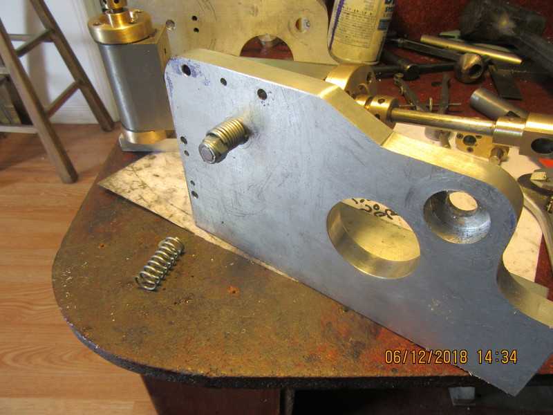
One more pretty picture before I go to bed. By putting a .045 deep counterbore at each port opening and a #10-24 threaded hole between them, I can bolt on my valve block with internal porting and set rubber O-rings in the counterbores to seal everything up. There may even be a possibility of building a reverse into the valve block, but my mind hasn't got that far yet.---And yes Charles, I plan on dowelling everything to maintain the relation ship between all the components of the frame.
HR9QGn.jpg
 
Sometimes you've just got to make big holes!! The largest hole here is 1.7" diameter. the smaller hole that breaks thru the end of the angle is 1 1/2" diameter. These were both done with the boring head in my milling machine. The biggest hole with metal all around it was pretty straightforward. The smaller hole that breaks thru the end of the angle was somewhat "clenchworthy". I drilled and bored both angles together, to ensure that all of the holes lined up. Anything that has a counterbore was drilled first with a clearance drill thru both angles, then counterbored on the near side only. I will have to separate the angles and flip the bottom one over to put the counterbores in the far side.
xwgHUm.jpg
 
Brian,

Double-Dog Dang. It looks simple and elegant at the same time, like I like good designs to look like.

And now, I have to wait and watch for the run, which will probably be nice to watch as well.

Thank you, as always, for your contributions,

--ShopShoe
 
The manifold is really quite simple, with an air inlet only. The only magic (which you can't see, but trust me) is that by taking out the two #10 shcs and flipping the manifold end for end I can reverse the rotation of the engine. In it's current configuration, the exhaust comes out the underside of the manifold. If I flip it over, the exhaust will come out the top side.
pyWGV1.jpg
 
Preliminary results are in from the first assembly and they are good. Everything goes round and round and up and down with no interference issues. The crankshaft is cut to length and keyways are cut and installed. I still have to finish that spreader angle with the blue layout dye on it, but so far things are great. I may even run an airline in and see what results I get. I haven't yet installed the proper pivots nor hold down springs for the cylinders, but I can hold them in by hand for a short test.
6jnZTp.jpg
 
EXCITEMENT rules the day.--It runs!! Not good enough for a video, and you need more arms than an octopus to hold the airgun and the frame and the cylinder, but it runs. Time to run up to Tim Hortons donu
 
Once I get this all buttoned up you will never get to see this. So--This is the compression spring and nylock nut that pull the flat base on the cylinder tight up against the side of the angle frame to minimize any air leaks. I don't have a lot of room between the angles when fully assembled, but there should be about 0.030" clearance between the two nylock nuts.
EjrXuO.jpg
 
Everything is back together. It is stiff, but I expected it to be. My butt is kicked for today, but tomorrow I hope to make the manifold and maybe get some air on it. A 1" diameter cylinder at 50 psi will give a force of 40 pounds, and this has two cylinders, so I expect any stiffness will give up fairly quickly with a total of 80 pounds of force acting on the crank arms.
 
-Probably Belleville washers would work fine instead of springs. I never even thought of anything but "compression spring". There is a rather delicate balance here, of having the springs exert enough force that all the air doesn't escape between the cylinder and the frame, and yet not so much force that the engine is too stiff to run. Since it is a brand new engine, I don't know if the stiffness in it comes as a result of spring compression too tight, or just accumulated tolerances on everything. Once I get it up and running, I will decide if I have to take a coil or two off the springs.---Brian
 
I have a couple of small single cylinder "wobblers" from early days ten years ago when I started machining. Brass 1/2" bore cylinders and aluminum frames. Never had a problem with them and was tickled pink when they actually ran. Fast forward ten years, and I have built what is a monster double wobbler compared to those early engines. If I have trouble with "galling" of the aluminum under the 1" bore cylinders, I may have to mill away 1/8" of aluminum and J.B. Weld a piece of cast iron or 660 bronze in the area where the cylinders pivot. Someone had suggested that earlier, but I decided to wait and see whether I would need to do it.---Brian
 
If I have trouble with "galling" of the aluminum under the 1" bore cylinders, I may have to mill away 1/8" of aluminum and J.B. Weld a piece of cast iron or 660 bronze in the area where the cylinders pivot.

You could try it with a bit of graphite grease or molly grease on the portfaces to start the running in.
 
So folks, here we have it. It runs just as well as I had hoped it would, and will self start with the crank throws at 90 degrees to each other. It runs on about 10 psi of air. This engine has the fewest parts of any engine I have ever built. If anyone would like to build this engine, I sell a complete set of plans for $25 Canadian funds. There are 23 drawings in the set, including general arrangements and bills of material. You can contact me at [email protected]
 
Last edited:
After 3/4 of an hour running, 80% of the stiffness is gone. Any residual friction is easily overcome by the power of the engine. I thought it would be like that, but I'm never sure until I've run a new engine for a while.
 
Another great Brian Rupnow project.

Thank you for your contributions in general and thank you for your thread on the build of this one.

If I were to build this, I would want a place to put a belt or add a geartrain for power output for running one of your little mechanical devices: I am curious how you would do it. My immediate approach would just be a belt groove in the flywheel, but I was just wondering ...

--ShopShoe
 
I wouldn't mess with the flywheel. Just make the spreader angle between the two side angles a bit longer, make the plain crankshaft a fit longer, and run a smaller pulley beside the flywheel.
 
As promised, here is the final video of the double cylinder oscillating engine. Please note that I misspoke in the voice-over and said it has a 2 3/4" stroke. That was wrong.--It has a 1 3/4" stroke.---Brian
 
Last edited:

Latest posts

Back
Top