Elmer's Pumping Engine

Home Model Engine Machinist Forum

Help Support Home Model Engine Machinist Forum:

This site may earn a commission from merchant affiliate links, including eBay, Amazon, and others.
Hey Dave
Thanks for asking. I've been making all of the little stuff that everyone has seen a million times.
I'll be doing a fairly long post tonight. Just have the intake and exhaust water thingies to do and then railings, etc.
This should hold you over until then

[ame]http://www.youtube.com/watch?v=anNb0OuI0v0&feature=youtube_gdata_player[/ame]
 
Whaddya mean its on backwards?

After completing the top end (engine parts), it seemed like a good time to do an assembly to see what needed tweaking (filing, debarring that was missed, large hammer.)

Disaster. I had minimal clearance between the yokes and the crank. With the pump piston in place, none of the mounting holes lined up. I disassembled and measured and compared every part to the drawings. Everything passed the QC Department but nothing seemed to fit correctly and had tight clearances.

Time for a single-malt and lengthy staring at the engine. It took way too long to realize that I had mounted the bearing support blocks backwards! The blocks have a cutout to allow the pump body to be positioned in toward the center. The absence of the cutout kept the pumps from aligning vertically with the piston rod and yoke. This led to minimal clearances, yada yada.

Disassembled the engine, reversed the blocks, reassembled and everything fit perfectly. Of course it did. It was designed that way.

"Stupid is as stupid does" Forrest Gump

So let's start with the damn bearing beams


Just your basic drilling and tapping. Found the center of the part and DRO'd everything from there.


I had left the part a few thou high to allow for cleanup after drilling. I find these Machinist Papers to be quite consistent in thickness at a hair over 1/1000"


Then a bevel all around with a 45 degree end mill. I think it gives the pieces more of a finished look.


Both completed here. Wet/dry finishing will follow.


As with Elmer's square cylinders on the radial engine, I'm not in love with Elmer's bearings (you know, rounded top to look like a faux bearing cap.). After sketching a few shapes I kept coming back to a round bearing. Part off a few disks of 6061.


Scribe a line and, using my precision positioning tool which is resting on the vise jaw, align the part horizontally.


Remove what I don't need


And end up with this


Now, pay close attention here to the orientation of the bearing supports. In case you weren't sure, these are BACKWARDS.


Now, some drilling of the yokes. I clamped them in a small grinder vise and then clamped that vise in my mill vise.


And line boring the bearings. (interestingly, when I removed the bearing supports to turn them around, the shaft had no binding)


At Cabin Fever, Scott (Cheepo45) mentioned that he had used some 1/16" E-clips to retain a pin.
This seemed like a much better idea than Elmer's wire-through-the-tiny-hole. Especially after I replaced the wire 3 times on the Grasshopper on Saturday at Cabin Fever.

I got a bag of 100 - 1/16th" E-clips from McMaster and found the dimensions for the groove width and diameter in Machinery Handbook. All the model airplane and model car guys seem to use these a lot and most of the advice on their forums was "needle nose pliers" for installation and removal.
Not in my world. I seemed to shoot 4 out of 5 into oblivion and was just about to go back to Elmer's wire retainers when I found this. A miracle tool. Every clip slid into the groove and snapped into place. Even in tight places in the engine. I think around $20 from Tower hobbies.


The clips are removed by pushing from the open end.


Done.


Next installment will be the pumps and valves. I'm closing in on the last of the parts, but have much more to do after that as soon as I'm happy with the COC drawings for the railings, stairs and floors.

Here's the first run of the top end (no pumps) running on around 8-10 pounds of air.

[ame]http://www.youtube.com/watch?v=anNb0OuI0v0[/ame]
 
Wow....extremely impressed. Excellent job with that engine! I will never look at ZigZag papers the same again after this post!
 
Great work, Stan! I will have to get one of those circlip tools.
cheepo45
 
Pumps, Bolts and Railings

I went into these parts totally blind. I've never built a pump. Never made anything that had ball valves, so I had to trust Elmer on these parts.

The pump cylinder is straight turning, drilling and boring. Nothing complex here.


A 7/16-20 internal thread for the pack nut completes this part.


The smaller diameter at the bottom will be soldered into a square mounting plate.


The pump pistons were a good fit but seemed a bit "scratchy" to me. I mounted each piston in a collet, mixed up a tiny bit of Extra Fine Timesaver with Mobil1 and that took care of it. The piston movement is very smooth with a bit of back pressure when i push them into the pump cylinder.


The pack nut drawings show a .500 hex bar for the nut. The assembly drawings show a knurled piece. I liked the look of the knurled nut and had another chance to use the shop-built knurling tool (Hemingway Kits)


Then thread, through drill for the piston rod and part off.


Pay very close attention to the above sequence: Thread, drill, part off.
Drilling before threading gives you this.


Eventually, you get these:


The pump baseplates


Ready for soldering.


The pump is threaded 3/16"-40 MTP (Model Taper Pipe). At Cabin Fever, I spent some time talking to the PM Research people about taper vs straight 3/16-40 threads. The major issue (that I forgot) is that I don't know of a way to make the taper tighten up AND have parts, like the intake and discharge valves, end up perfectly vertical. PM Research feels that the straight thread, with Loctite works just fine.


The intake and discharge valves have two internal diameters. The larger is to be flat-bottomed. I drilled for the smaller diameter and then followed up with a 5/16" end mill for the flat bottom section. Finally a boring bar to .272


Here are the 4 valve bodies.


A set of matching valve covers. I first marked out the major points.


Then turning, threading and parting off.


A bit of filing and polishing to finish these.


Off to the mill to drill the valve bodies for the 3/16" tubing. Note the Harbor Freight 3/16" drill bit.


Now, note the hole with a piece of 3/16" tubing inserted.


After that, I went a few drill sizes under and reamed to a thou over. Much better fit


The 3/16" tubing that I had was fairly thick walled. Not wanting to impede what I'm sure will be a torrent of water from the pumps, I drilled the pipes to a larger I.D.


Ready for soldering. The blue-gray stuff is "anti-flux" so that I don't have solder all over valves.


The final pieces of the pump saga are the mounting bolts. Simple job with 3/16" hex.


Some polishing and a manicure finished the 4-40 bolts


A start for the railings

Elmer's drawings show 3/32" square stock for the railing top with square corners.
A. I had no 3/32" square stock
B. I don't remember ever seeing a factory railing that wasn't round.

After bending some not-attractive samples, I built this with some dowel pins. The scribe line allows a fairly precise placement of the mark for the radius center.


I found the the best looking bend came with hammering the rod around the corner with this, quite attractive ,drift. (a mismade part from another engine)


Another test. Even with very light pressure when center drilling, the damn center drill was not happy about staying on center and of course this drill bit liked it even less.


I very slightly flattened the top with a 1/16" end mill and that solved the problem.


Once the holes are drilled in the table for the railing balusters, I can move to the next railing piece.


Getting closer a part at a time.
 
Maybe I'm a little strange (Hell, maybe I'm a LOT strange!!!) but I prefer the look of flywheels at this stage. Oh, I know, cut outs make it easier to see the engines running, and they are the accepted "norm" but there is something about plain flywheels that really appeals to me.---Brian
 
Brian
It would have been a whole lot easier to leave it like that

Best
Stan
 
Stan,
Incredible documentation. Anyone who has ever done a WIP can appreciate your stopping midstream to take these photos. The e-clip tool reference was a bonus for anyone following this thread. Thm:Thm:Thm:Thm:

Cheers,
Phil
 
The old adage "a picture says a thousand words" is well demonstrated by your excellent use of macro photos and lighting.
 
Sometimes, Elmer just annoys me.

The engines run. They are, for the most part, not terribly difficult to build, but I get the impression that once Elmer had a runner, he said, "O.K., that's done. Next." Not a lot of thought to aesthetics. Case in point: The three cylinder radial. Square cylinders? Come on Elmer. When I built that one, I hated those square cylinders and so, after many hours of figuring how to run the air without external piping, cut cooling fins (just because they looked good), etc., that was done.

Occasionally, Elmer would throw in a "decorative" column. Most look like a second-hand, Victorian table leg. Which brings me to the current build: Elmer's Pumping Engine. It runs, it pumps. It's actually one of his more interesting designs with the catwalks and the unique shape to the yokes.

I don't call an engine done until the tool marks are removed and has been shined up a bit (OK, a lot.) so this one was just to the phase where I was ready to take it apart and begin polishing. I did have one more piece to do: the ladder and the longer I looked at it, the more I thought it was out of scale with the rest of the engine. Initially I was going to scale it down to a more pleasing proportion. Then I thought about going a completely different route. "Why not a spiral stair with brass balusters and railing." "Hey, let's do the stair treads in diamond plate. Can't take that much time." So, two weeks later...

I began by cutting a handful of aluminum blanks for the steps on the bandsaw.


The 2" face mill did a nice job of evening everything out so I was, at least, beginning with blanks that were the same size. It doesn't read well in the photo but there is thin cardboard packing to account for size variations in the width of the blanks.


I flipped the stack and through-drilled. Lots of peck drilling here as the drill bit was in deep and the chips had no place to go.


Once the hole was drilled (it will also be the hole for the center post), I bolted the plates together and set it up in the sine vise. I wasn't actually using the sine vise to set the angle but it was a good size for this. I pretty much eyeballed the fan angle of the steps.


With the stair treads shaped, I was going to set up the rotary table to round over the ends while still bolted together. Or not…


That was much easier and I didn't have to re-indicate the vise when I was finished. Thank you, Oliver.

I had decided on two steps up to the stair and a round base appealed to me. Rough cut a circle on the bandsaw and turned this. It will be painted black.


The balusters will be brass with a rounded top and a 40 degree hole to accommodate the handrail. I sort of held a protractor and said, "that looks about right for the angle."

The round top was done with a corner-rounding end mill in a QCTP holder at the lathe. Quick and easy.


Parted off, reversed in the collet and threaded 2-56.


Back at the mill, I put a baluster in a square collet block, set an adjustable angle thingee at 40 degrees and clamped all to an angle plate.


Very carefully found center (.095 rod with a .0625 hole)


The only way I could see to drill at a 40 degree angle was with an end mill.


Since I had 10 steps (later reduced to eight) to drill and tap for the balusters, I made a locating fixture.


The time spent making the fixture was well spent. All holes in the same place. No multiple setups.


Those parts are done.


Did I mention the crazy idea about diamond plate stair treads? I'm pretty sure that a CNC mill could have done it. This was perfect.


I put tape on each tread. (I know. The VHB is a bit of overkill but I didn't feel like driving to get carpet tape)


Trimmed to size.


Holes were drilled through the plastic diamond plate by hand. The material is quite thin and loves to catch on the drill bit and tear.


Into the State-of-the-Art paint booth they went.


Ready for assembly


And done. Now I can disassemble the engine, get it polished and finish. This has gone on way too long and I have a PM Research Horizontal boiler waiting to be built. Thanks, Elmer.

 
Stan, man that looks great. Your showing off with the spiral stairs :D

Dave
 
Stan

Thanks for a superb build log, I've just started my build of this engine and expect to make extensive use of your prior experience.

As for the spiral stairway - not very Elmer, but very posh and certainly one of the most ambitious embellishments of these engines I've seen.

I see the staircase to the catwalk, any plans to extend it to the table?

Kind regards

Geoff at Inky Engines
 
Geoff
Thank you. Your comments are much appreciated. I had originally planned a spiral to the top with platforms extending to it from the catwalk and top table. Centering in the front didn't work due to the pumps and the water tank that will be placed there. The other issue in placing it on that face was the exit from the stairs would be directly into the flywheel. Thus, I moved it to the side. The problem in extending it took the top table was exiting into the cylinders. So it ends at the catwalk. I'm looking at dual, properly proportioned ladders from the catwalk to the top table. Either that or let the engine maintenance people bring their own damn ladder.
 
I think that the end is near.

I've completely disassembled the engine and am beginning to detail, file and polish.

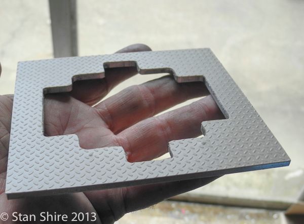
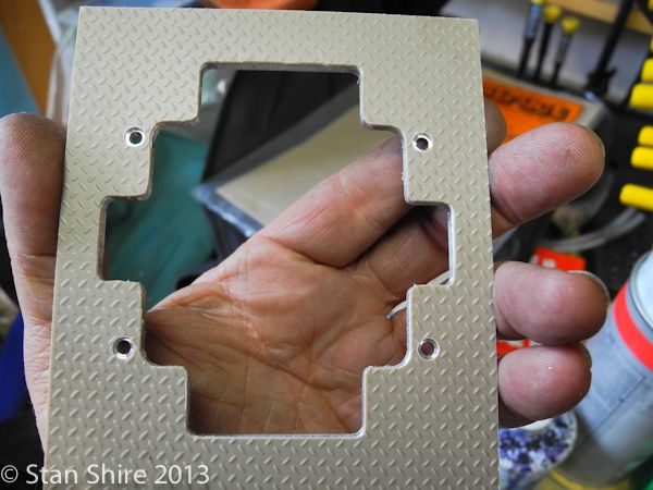
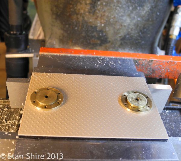
The table and catwalk have diamond plate. When I put it on, I didn't want parts resting on it. I was concerned that the uneven surface might cause some "issues" and I'd rather have parts firmly touching actual metal, instead of plastic. The solution was to mill away the plastic in those areas.

In an earlier post I had made a bending jig for the railings, but after gazing at that railing for a week or two, I decided to scrap that design and make a flat top railing. I liked the width and it seemed like a more substantial line.

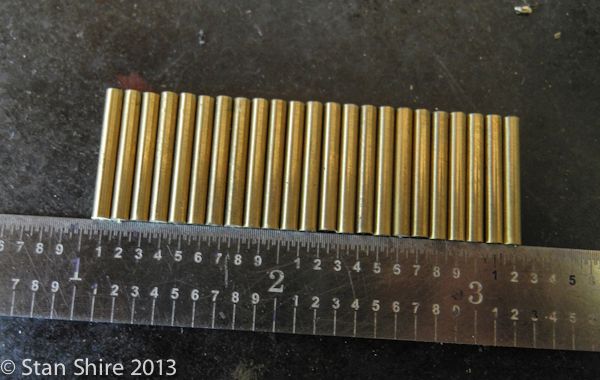
Now I need 28 posts that are the same length. If they are "pretty close", as they were on the original railing, getting all of them to drop into holes and keep the railing level is not something that I wanted to repeat.

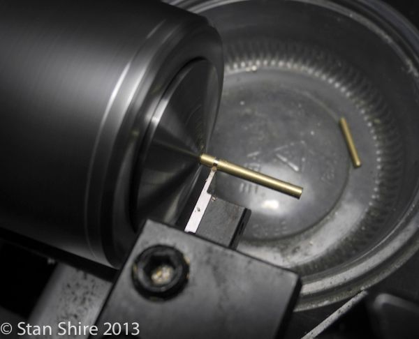
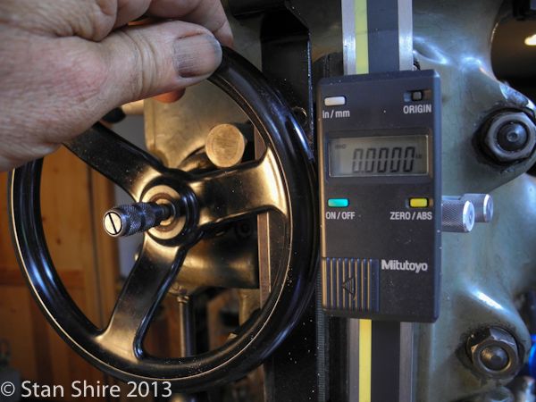
With a 12" piece of brass rod in the 5C collet, the collet was tightened just enough to allow the rod to slide.


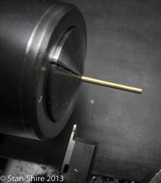
Then a piece of brass tubing, as a depth gauge, was slid on.


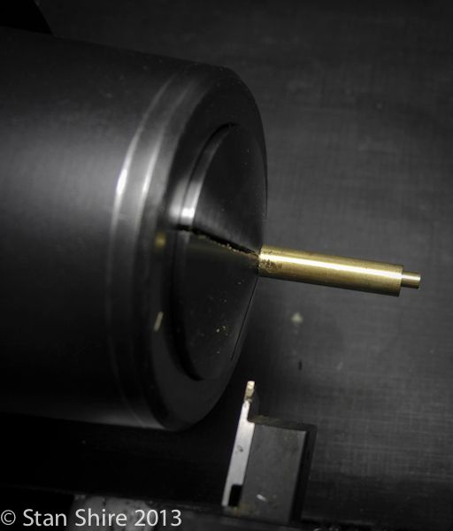
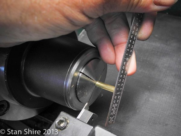
A scale was handy, so I used that to press the rod back so that it was flush with the tubing and the chuck tightened.


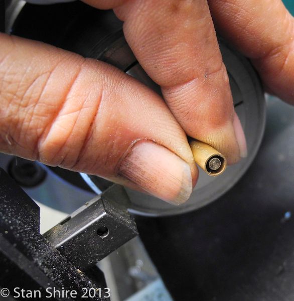
Parted off into the collection tub. These tubs, with snap on lids, are the main reason I occasionally stop at KFC. (Kentucky Fried Chicken if you don't have them in your neck of the woods)


That finishes the first group of posts.


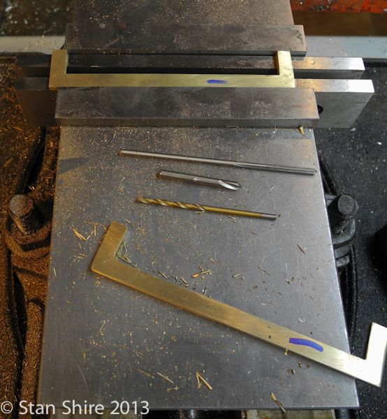
The railing tops were done with flat stock. Cut, mitered, soldered, filed and generally beaten into submission.
Each hole was drilled then reamed .001 over the diameter of the posts for a sliding fit. The hole depth was slightly over ½ the thickness of the brass flatbar.


The posts did end up level. Test fit here.


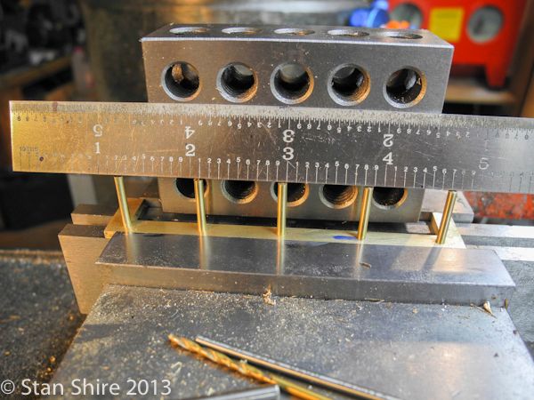
Drilling the blind holes to the same depth was easier than I thought. For some reason, many people on the various Bridgeport forums, never use the hand wheel to move the quill for drilling and, in fact, don't like it or have no idea when it was last seen.
I found that I could accurately move the quill in .0005 increments.


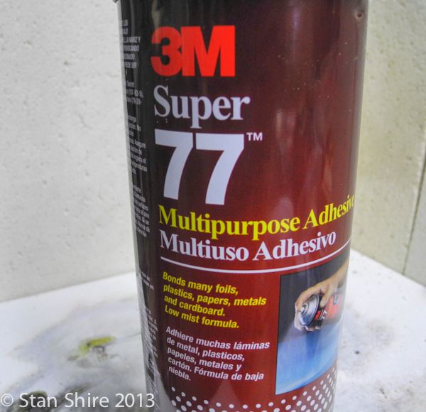
The Plastruct diamond plate now gets attached to the table and catwalk. Plastruct recommended this adhesive. Spray the Plastruct and spray the aluminum. Wait 30 seconds and press together.


An Xacto knife with #11 blade was used to cutout the opening in the Plastruct.


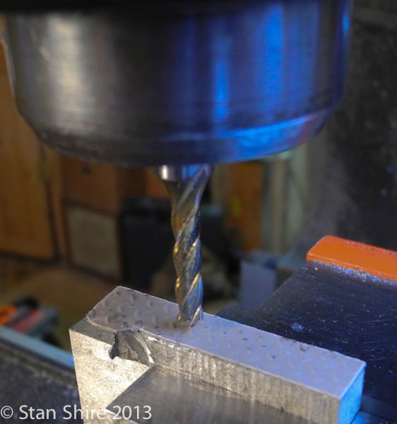
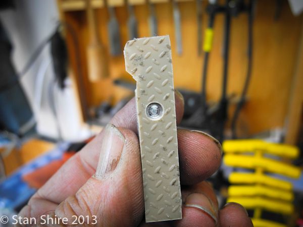
As I mentioned, I wanted to mill the diamond plate down to the aluminum. I was concerned that the end mill might muck up the plastic, so I attached a test piece to a scrap of 6061. No problem at all.
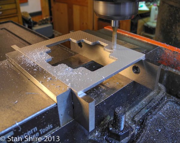
Again, I used the hand wheel and milled to the thickness of the diamond plate.


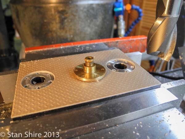
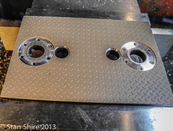
With the parts in the vise, I milled the plastic where I wanted metal-to-metal contact.


Painted the table and catwalk with gloss black spray enamel. Not concerned about the edges. They'll be finished a bit differently.

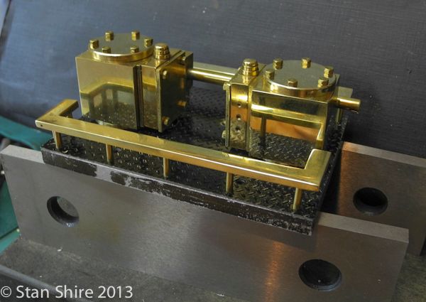
Most polishing done here and railing Loctited in place.


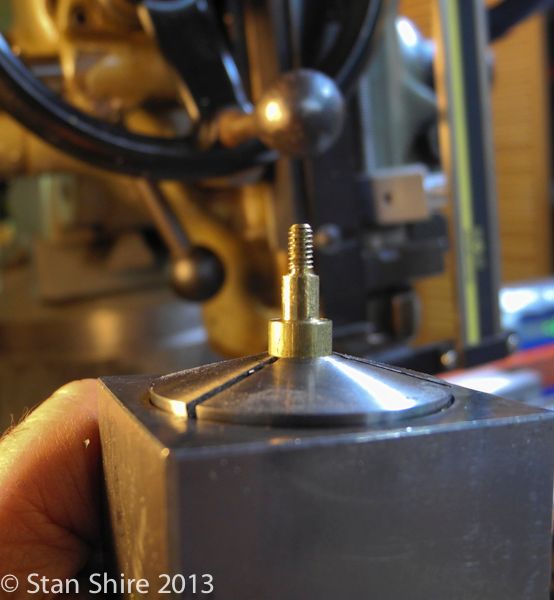
The next activity was to make the final adjustments a bit easier. Screwing the pump pistons up into the yoke is a "character-building exercise."
I wrapped small pliers with tape to prevent scratching as I turned the piston. The tape didn't do a great job and the entire process was generally a PITA.

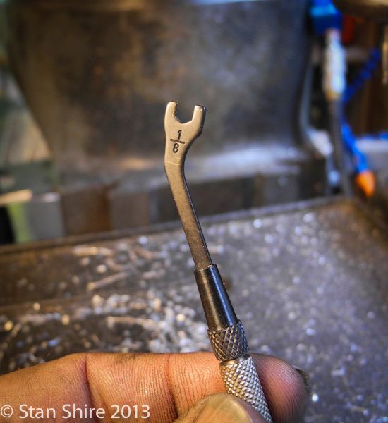
I decided to mill flats on the shaft for a ⅛" open-end wrench.

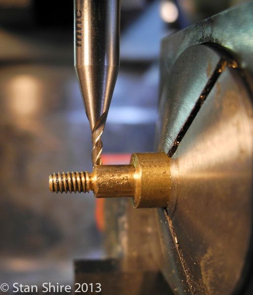
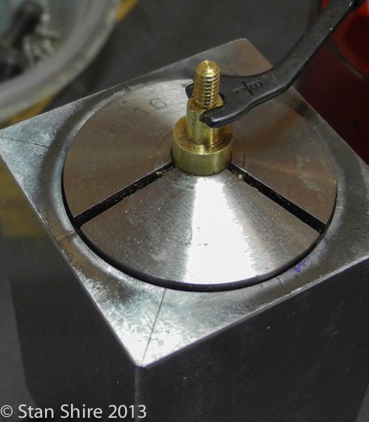
Quick work. Pump piston in 5C collet and then into a square collet block.


IMHO, the best tiny wrenches ever. Moody Tools. Made in USA somewhere. Beautiful tools.


1/16" end mill. .030 depth of cut. Very slow crank on Y axis handles.


Rotate collet block 180 and repeat.

Done.


Nearly ready to reassemble. Then I can begin the pipefitting for the pump intakes and exhausts. The 3/16' fittings and unions arrived the other day from PM Research and a few inches of 3" O.D.brass for a water tank from Online Metals. I love the ability to order by the inch.

Thanks for watching
Stan
 

Latest posts

Back
Top