Kozo A3 in 1.5" scale

Home Model Engine Machinist Forum

Help Support Home Model Engine Machinist Forum:

This site may earn a commission from merchant affiliate links, including eBay, Amazon, and others.
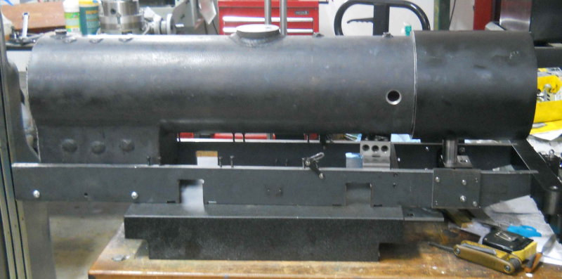
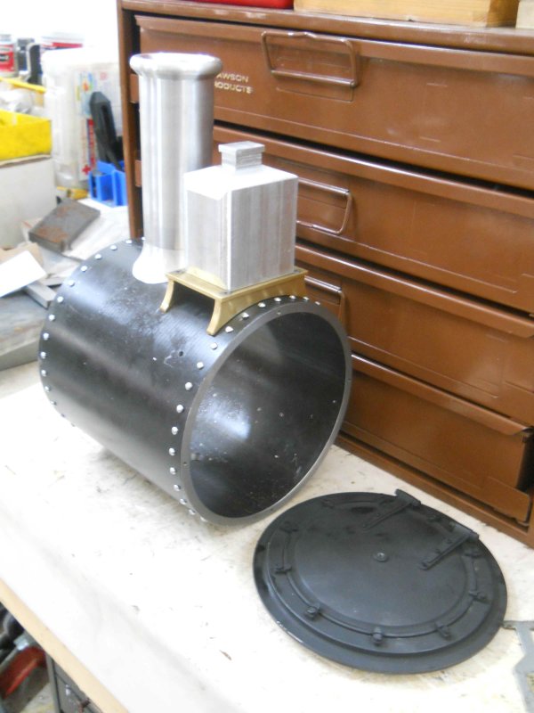
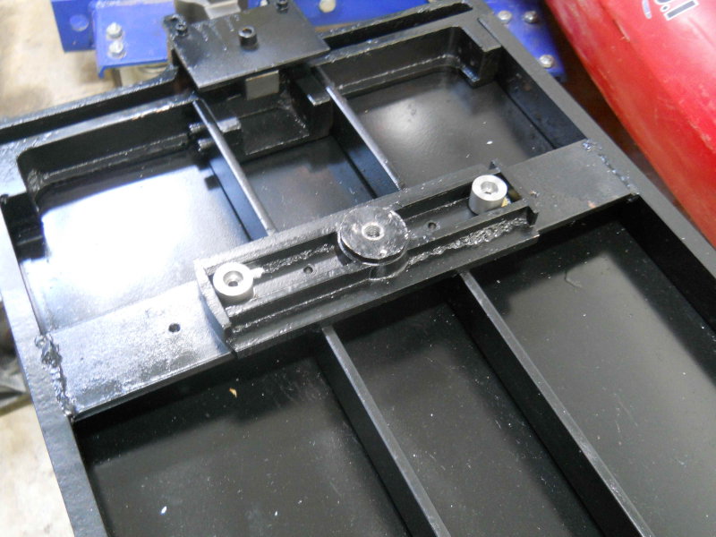
Today I painted the frame and tank of the tender (separately). Here's the tank:

large.jpg


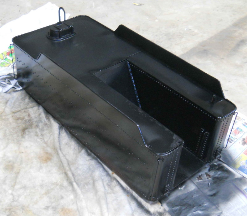
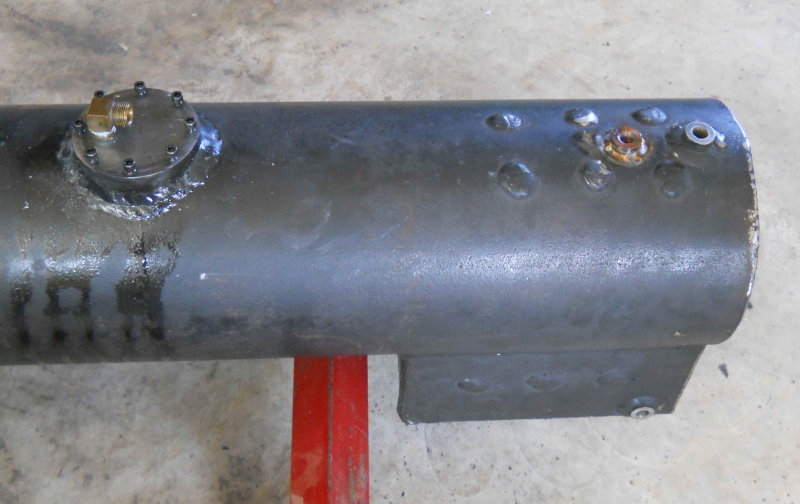
I found that the beading around the upper edges are indeed brass, so I'm not sure how well the paint will adhere. It will get a second coat tomorrow.

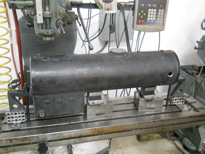
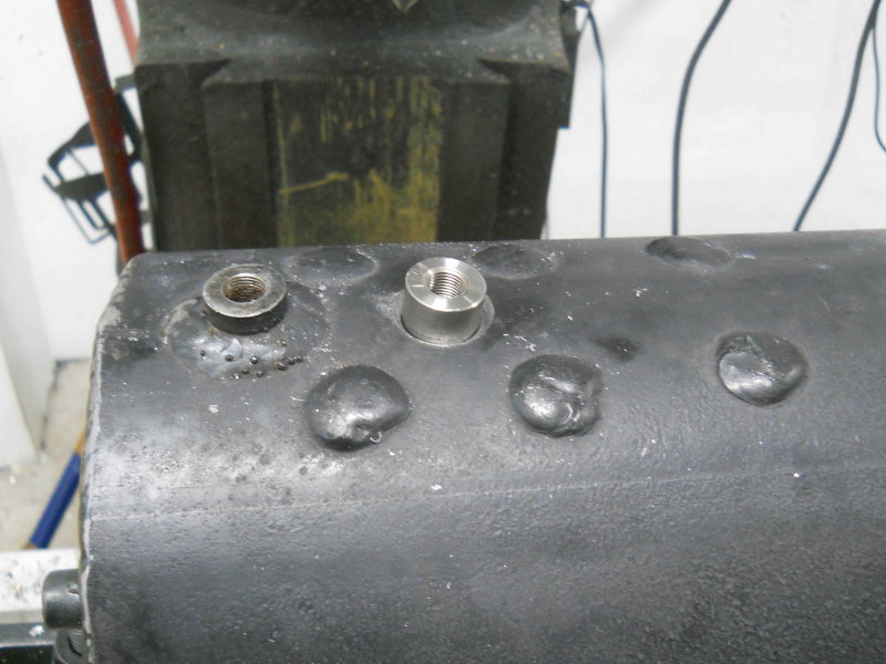
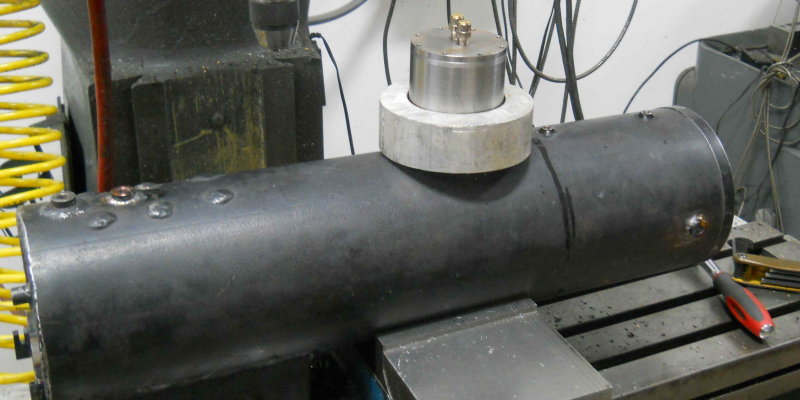
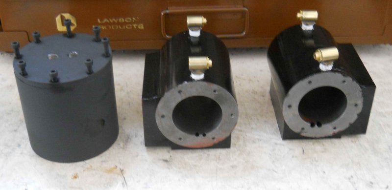
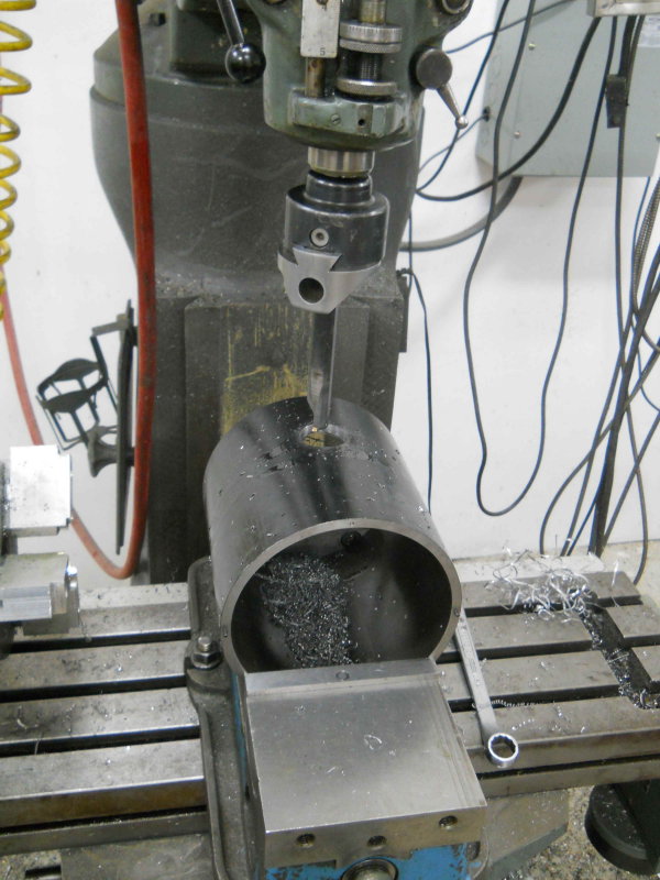
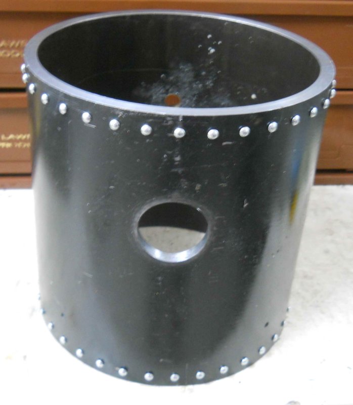
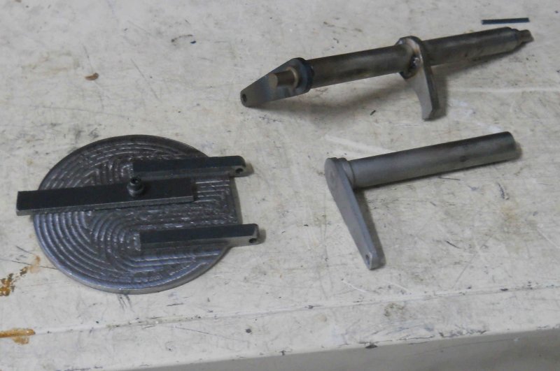
Yesterday I took the boiler over to a fellow club member's house where he Tig'ed the ring for the firebox door onto the boiler. He also tig'ed the brake lever parts where I'd had difficulty attaching them with silver solder:

large.jpg


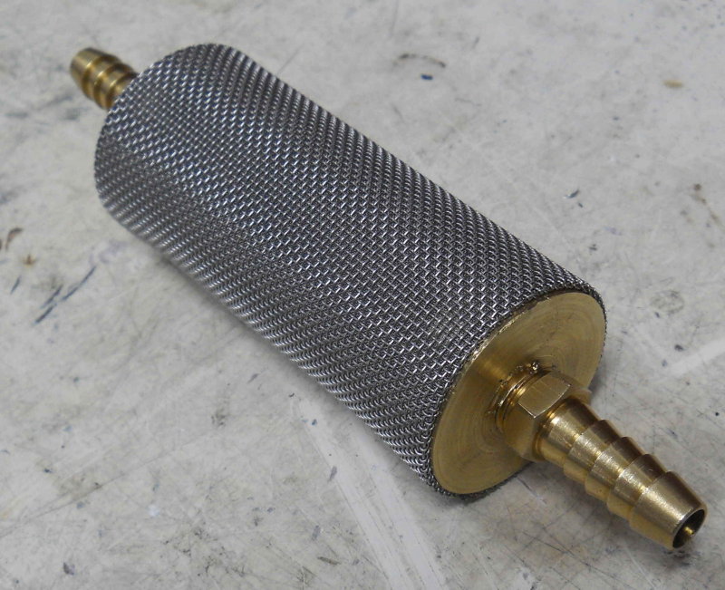
Finally, I bought a spray basket strainer at Tractor Supply. It has an 80-mesh strainer as shown here:

large.jpg


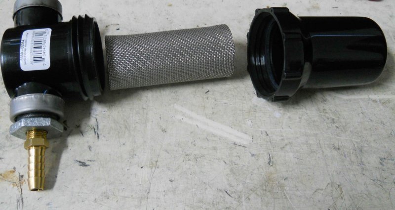
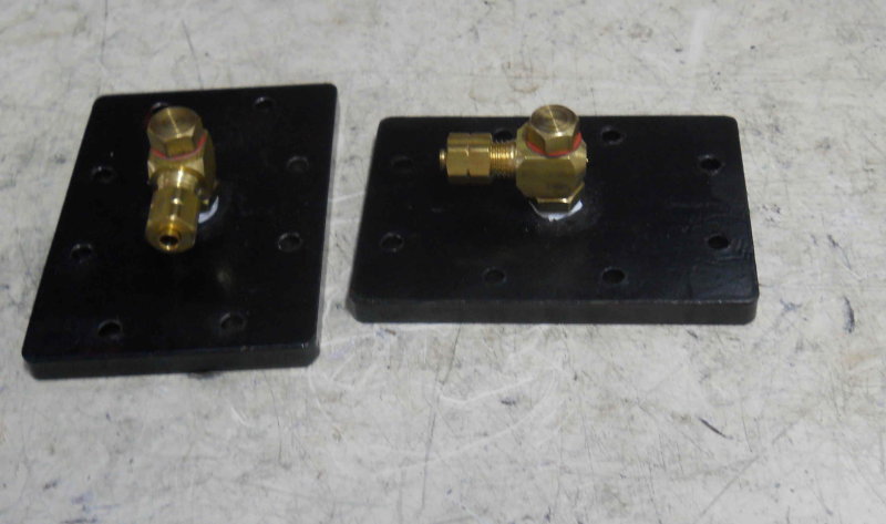
Since I'm going to be using injectors, the tender water supply needs to be strained to prevent small particles in the water from clogging the injector. My tender is not well suited for putting a well in the bottom, so I was planning to use this strainer inside the tank to connect to the valves via tubing. However, the size and design of the plastic enclosure makes this a no-go. So I plan to make caps for the ends of the strainer basket and connect both valves via barbs and tubing.
 
Today did touchup on the tender paint, and then made this using the strainer basket:

large.jpg


The two plugs on each end were tapered to ensure a nice tight fit. This filter will be connected by plastic tubes to the two water valves.
 
I took the tender to the club today for a short test on the rails. I don't have a seat yet, but sitting on the rear cover with feet on the footrests is reasonably comfortable, and should improve with a seat and more height. Since the engine has a footbrake pedal, I have yet to see where the right foot would best be placed when running.

The good news is that the trucks tracked well while being pulled/pushed with a fellow-member's diesel. The bad is that there is excessive side rock, and I will need to add some pads to the tender's bolsters. Being in bright sun also showed up lots of spots that need another paint layer.

This weekend I started preparing the bushings in the boiler for the feed water checks and glass/pressure gauges, and tonight I finished up ready for welding. This technique, which a fellow club member recommends, is best done early in the build where they can be welded on both sides of the pipe. The bushings are made from SS high-pressure couplings purchased from the hardware. In this case, the couplings are 3/4" diameter, ~2" long, and threaded 1/4 NPT on each end. Each coupling yields two bushings when cut in two. I cut them on the lathe with a 1/16 parting tool using lots of cutting oil.

Another reason to weld everything early on is the difficulty of securing a finished boiler to the mill table. here's my setup for the feed water holes:

large.jpg


The tube is resting on two largish v-blocks with the jack supporting the firebox. A square against the steam dome plate makes the boiler as close to sideways as I could get. The it's drill out to 11/16, and bore to ~.730. Then countersink about halfway to provide space for weld filler.

large.jpg


The bushing measured .747, and as dropping it through the hole would be both embarrassing and a PITA, I necked down the bushing part way until there is a tight fit.

large.jpg


The other side was done the same way after rotating the tube on the v-blocks and re-clamping. The third bushing will supply steam to the water glass and pressure gauge. Kozo's design connects both to the turret, and I've been advised that this is poor practice at larger scales, because any valve open in the turret drops pressure and caused both gauges to fluctuate. The same drilling/boring/countersinking was done for this with a different, somewhat "jury-rigged" setup:

large.jpg


large.jpg


I still need to drill and tap a hole in the backhead for the water gauge. I was able to use the top bushing hole to measure the depth of the crown sheet as 2.4". Since I want the bottom of the glass to be .5" above, that will be 1.9" from the top of the tube. And since the glass I will be using has its connection 1.25" below the glass, I can drill the hole anywhere in the backhead 3.15" below the top. I'll have to wait and see how far to the side I want the glass at some point. Since I don't have a 90 degree head for the Bridgeport, I'll have to mount the boiler with the tube hanging vertically off the back of the table, and turn/extent the ram to reach the desired spot.
 
While waiting for my buddy to weld up the bushings, I proceeded to try to muddle along and see if i could get the smokebox height to match the boiler's when mounted to the frame supports. Since the smokebox is supported by the tee, the top of the tee will be the reference datum. Since the tee is connected to the frame by the cylinders, which would be in the way, I machined a couple of support plates using the cylinders' hole pattern. This way I can hold the tee in its proper position without the cylinders:

large.jpg


Now I rmoved the wheels and axles, placed the frame on the surface plate, and used my electronic level to measure the top of the tee:

large.jpg


Now with the boiler in place, I added some supports to get the same measurement, using the smokebox plate as a datum:

large.jpg


Now by measuring the top of the boiler tube from the tee, and knowing both the boiler and smokebox ODs, I calculated the necessary length of the smokebox support. It was less than I made it originally, so I faced it off in the lathe and did a quick fit:

large.jpg


I still need to tap the support and secure the smokebox with the nozzle. Since the support screws into the tee, I can adjust the smokebox height a bit once it's all together.
 
Another thread I'm happy to find still going after my hiatus!
Looking great!
I've got the books and the dream and learning a lot here.

I noticed you were at Cabin Fever. Too bad I couldn't make it this year.
That was some trip you took!
 
Coming together nice KVOM!

Take your time on the boiler....it's time well spent.

Dave
 
A lot of little jobs done since the last post. My friend welded the bushings in the boiler and I received the steam dome and safeties from my boilermaker. In the meantime I tore down the frame completely and painted the side frames with Valspar tractor and implement paint after a coat of Valspar primer. I've also painted the steam chests.

Before painting I also drilled a hole in the right side frame for the blowdown valve (Kozo has only one on the left for the 3/4 scale model). I think that for 1.5 scale builders it's probably better to drill these holes after the boiler is finished, esp. if you're using a steel boiler. I found that the hole center needed to be a bit higher than per plan since there is weldment on the bottom of the firebox.

Here's a photo of the boiler with the steam dome and safeties, along with the hunk of aluminum that might become the base of the dome cover eventually.

large.jpg


The dome canister sits here held on by screws.

large.jpg


I am still undecided as to the throttle setup. The boiler was made to plan, but I've been advised that the needle valve Kozo shows for 3/4 scale is not best for larger scales, so I will be using a ball valve. The first option is for the valve to be vertical in the dome, and will need two elbows to position it in the center. I spec'ed the cylinder to be large enough to accomodate this setup. Then there are two possibilities:

1) have the valve stem exit the side of the dome and have the throttle be an exterior push-pull rod.
2) have the vale stem exit the back of the dome and the throttle will be an arm that rotates.

The final possibilitity may be to cut out the dry pipe from the front tube sheet, cut out the center of the dome to allow the valve to be inside the boiler, and run the throttle rod back through the backhead. Hopefully the brain trust at my club will come up with the best option.

The final bit done is to drill and tap holes for the cylinder cocks. Rather than make the fairly complex linkage Kozo designed, I decided to use a set of automatic cocks from Jesse Banning at JdLocomotive Works. These are threaded 1/8 NPT rather than the straight threads in Kozo's plans. If you inspect fig. 14-1 on p. 83, you see that the holes that actually enter the cylinder bore are angled. I have been advised that the angle is relatively unimportant as long as the piston rings don't pass over the holes; however, the closer the holes are to the end of the bore the better. I drew the holes in CAD to determine the angle, which seems to be 16 degrees, but I'm going to double check before drilling. These holes with be 1/8" diameter.

large.jpg


Then I can do some finish filing on the outside of the cylinders and paint them.
 
A few months ago I started to drill oil passages in the axles so that the axle boxes could be lubricated by ball oilers in the end of the axles. Then I had the drill bit break in the second side hole, so abandoned going further. I was pretty sure I would need to make new axles, since drilling them before the drivers were in place would be a lot easier. Before doing so, I decided to make one more try with the current axles.

Since then I acquired a small machinist vise, and this allows me to hold the axles/driver assembly above the mill vise. So with the following setup, a new 3/32 cobalt drill bit, and careful pecking, I drilled the lateral holes in one axle successfully.

large.jpg


I think I have figured out a way to drill the lengthwise holes as well. On the other axle, the broken bit is still lodged in the hole, so I am hoping that a carbide bit will be able to clear it out of the way.
 
Using the same small vise and a machinist's jack, I got this setup to enable drilling the lengthwise oil passages in the rear axle:

large.jpg


When trying the front axle on the side where the drill broke previously, I found it very hard to make any penetration. I suspect that the steel has hardened. When quartering last year, I had to remove the wheel and reposition it, and needed a torch to break the loctite seal. It never got red-hot nor was quenched, so I wouldn't have thought it would have gotten hard. I can get somewhere with carbide, so will try again tomorrow.
 
I set the axle oiler problem aside today and drilled the holes from the cocks into the cylinder bore, then finshed some cleanup of the outsides via some milling and sanding. Then I attached the steam chest covers and the mounting plates I made to align the tee to the valve and tee surfaces and applied painters tape to the ends. Thus all surfaces that are not to be painted are covered. With a couple of plugs in the threaded cylinder cock holes the cylinders are ready to be painted.

I'm going offroading with the Jeep tomorrow, so no more work until Sunday at the earliest.
 
I got the cylinders painted and the cocks installed. Also painted the steam dome and its cover with high-temp paint.

large.jpg


Then drilled and tapped the steam chest covers to install the lubricator check valves.

large.jpg


Saturday is hydro-test day at the club, so today I carried the boiler over there; I have a conflict in the morning, so hopefully it can be hydro'ed without me, or wait until I can get there.
 
I bit the bullet today and removed the front drivers from their axle. Since Loctite 620 frees up above 450F, I put the assembly in the oven at 500F for about 15 minutes. Then I used the shop press to separate the drivers from the axle. It took a fair amount of pressure before the axle let go with a "bang". On the other hand, the crank pins pressed out very easily. Then I turned a new axle with oiler passages:

large.jpg


My little bottle of 620 has gone missing in the shop, so after looking for it for half an hour I ordered a new bottle from McMaster. It should get here tomorrow so that I can re-quarter the drivers.

The only other little job I got done (finally) was drill some 1/16" oil holes in the eccentric rods.
 
This morning I re-quartered the front drivers using a method similar to how I did it last year at school. Now that I have some v-blocks with clamps I could do them at home. Here's the setup on the surface plate:

large.jpg


The driver on the left was fastened to the axle a couple of days ago. The two aluminum "fixtures" were turned so that the smaller diameter fits the crank pin holes, and the larger diameter mathches the axle. First I set the left driver with the crank vertical by matching the axle and fixture using a precision square. The v-block clamps are then secured. Next I measure the height of the right axle with a height gauge, subtract the axle diameter, and assemble a stack of gauge blocks equal to that amount. This stack then just fits under the axle. The longer aluminum rod held in the small vise is just the desired separation between the drivers.

So now the tricky part requiring some coordination: spread some green 620 Loctite inside the bore of the right driver, then slide the driver onto the axle so that it touches the end of the aluminum spacer rod, and then rotate so that the fixture rod touches the top of the gauge block stack. The Loctite gives you only a few seconds before it tightens up, so I did more a few dry run rehearsals.

I'll check my work in a day or so when I reassemble the frame; if all's well the two pairs of drivers attached with the side rods should turn freely again w/o binding. Then I'll secure the crank pins again with Loctite.

The "technique" is not all that different from what Kozo specifies, except that I could compensate for whatever axle diameter I chose.

I had ordered several boxes of drive screws to be used as fake rivets. After installing them into some scrap, I decided that the #4 screws would look best along the ends of the smokebox. I decided on 10 degrees separation as giving a decent look and making it easy to operate the rotab. Before the end of the session I managed to drill the rear holes and spot drill the front:

large.jpg


These screws use a #37 (.104") hole. I made a drift from some brass rod with a hemispherical cavity that I created with a 1/4 ball end mill. These should get installed next shop session. I had intended to bore the smokestack opening as well, but this setup isn't rigid enough.
 
Very interesting build, with lots of solutions to tricky problems! I'm following along with interest!

Simon
 
Continuing to work on the smokebox. Drilled and then bored the smoke hole to match the stack ID:

large.jpg


After finishing the "rivet" holes, installed the drive screws around the front and back perimeter. It should look better once the heads are painted to match the shell.

large.jpg


Couldn't resist a poser shot with the yet to be attached stack and headlight base:

large.jpg
 
Dear kvom
I'm really fascinated by your work!!!
 
Slow progress over the past week as life gets in the way and my mill was out of commission for a few days remaking the drawbar threads.

Managed to cut out the sides of the ash pan - 16 ga sheet. I'm going to make the bottom and front side from 1/8.

large.jpg


My solution to excess side play in the tender bolsters is these four round "pads", one on each side of each bolster. .75" diameter and countersunk, the side-to-side wobble is now the recommended 1/16 inch.

large.jpg
 
kvom said:
My solution to excess side play in the tender bolsters is these four round "pads", one on each side of each bolster. .75" diameter and countersunk, the side-to-side wobble is now the recommended 1/16 inch.

Could it be that those recesses were originally for nylon or Teflon pads?

Pete
 
The tender was made quite some time ago, and obviously was intended for a different set of trucks. I doubt any truck pads would be narrow enough to contact the recesses. It seems to be that the bolster was fabricated just to give enough clearance and to use minimal material.
 

Latest posts

Back
Top