Mitchg07261995
Senior Member
- Joined
- Nov 12, 2012
- Messages
- 242
- Reaction score
- 53
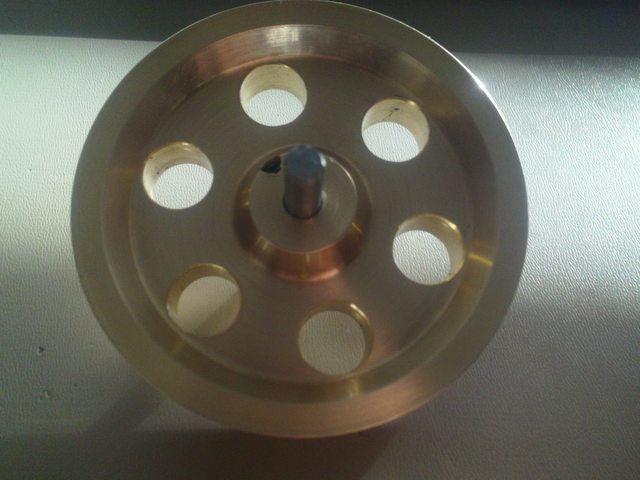
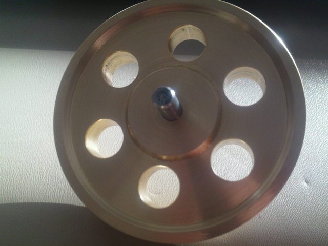
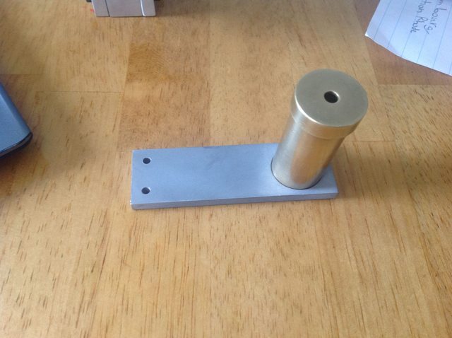
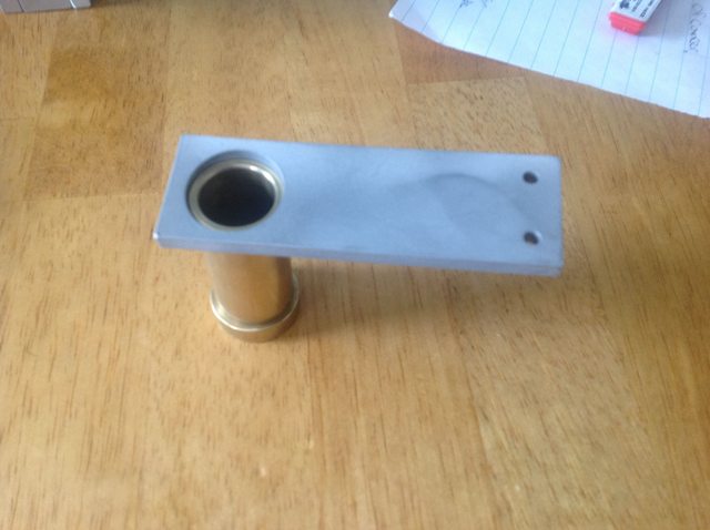
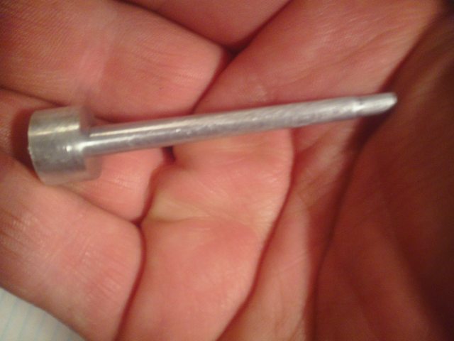
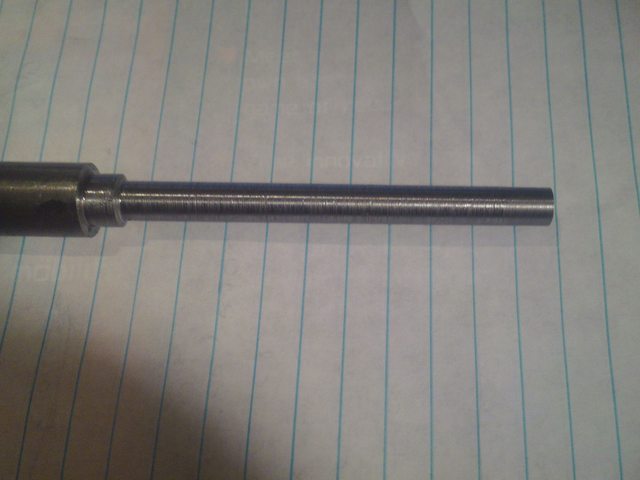
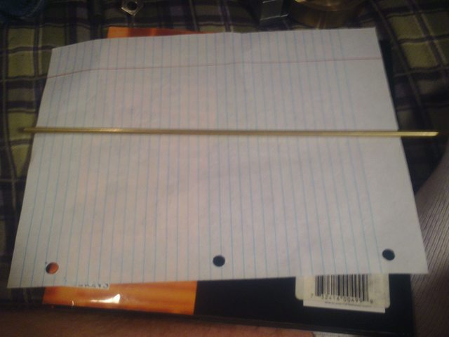
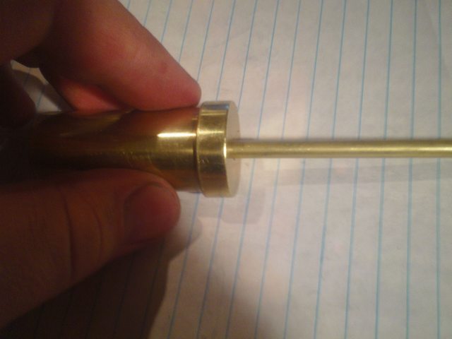
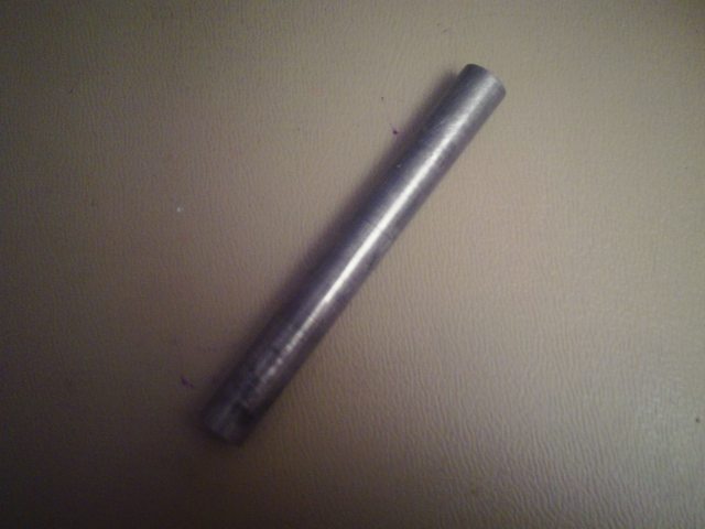
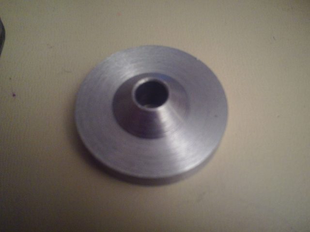
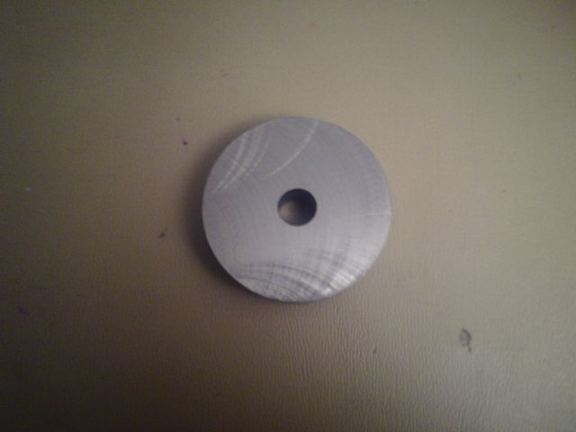
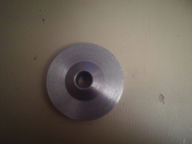
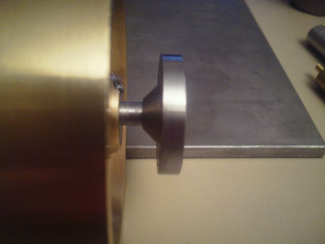
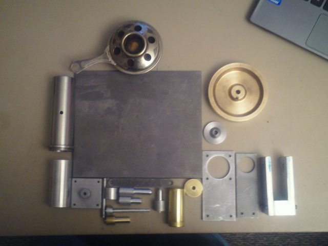
got some more work done today, one more part is finished the whole in the top just needs to be enlarged a little. Maybe .002'' im going about doing this by sanding it till the part that goes in the whole is a press fit
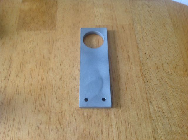
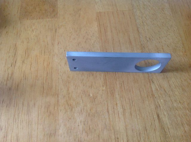
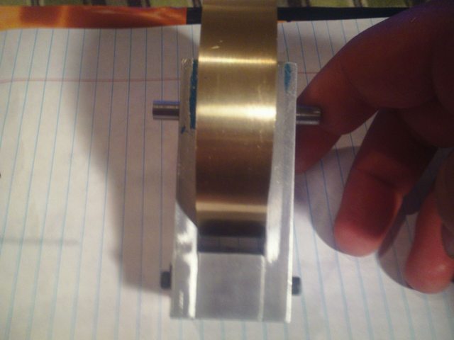
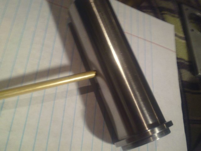
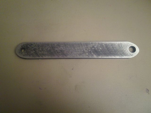
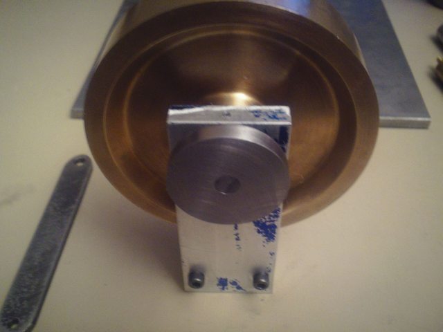
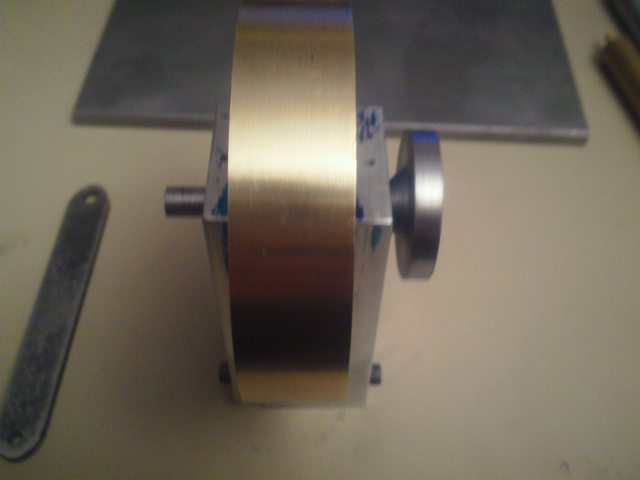
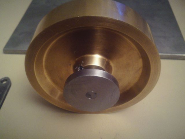
i modified the piece that my pal gave me, I need to make the space in between the part a little more wide so im taking about .010 at a time till i get the clearence for the flywheel that I need
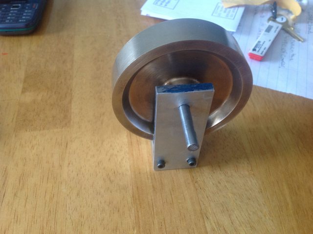
thats all for now
Mitch
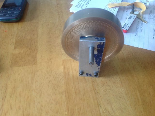
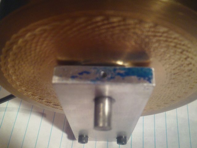
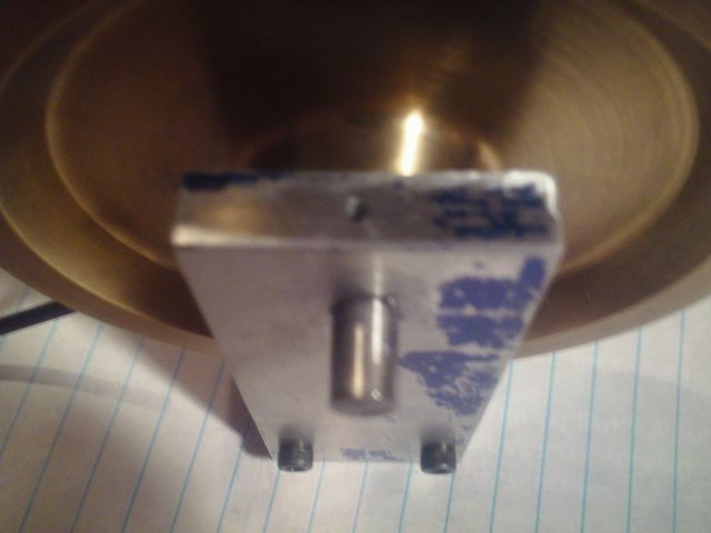
i modified the piece that my pal gave me, I need to make the space in between the part a little more wide so im taking about .010 at a time till i get the clearence for the flywheel that I need
thats all for now
Mitch
")