Zero-seven Hit & Miss

Home Model Engine Machinist Forum

Help Support Home Model Engine Machinist Forum:

This site may earn a commission from merchant affiliate links, including eBay, Amazon, and others.

Jasonb

Project of the Month Winner!!!
Project of the Month Winner
Joined
Mar 30, 2008
Messages
3,807
Reaction score
1,289
Location
Surrey, UK
Here in the UK the choice of Hit & Miss engines available to the model engineer is very limited compared to the US. I had almost resolved to the fact I would have to make the "little wonder" when MEB dropped on the doormat with the zero-six hit & miss design inside.

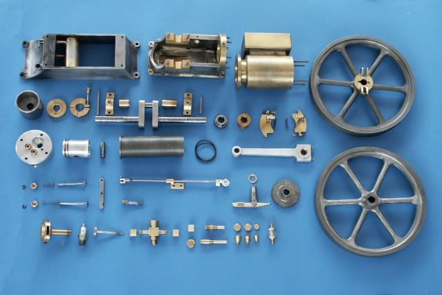
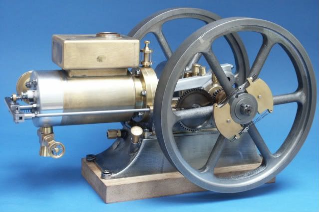
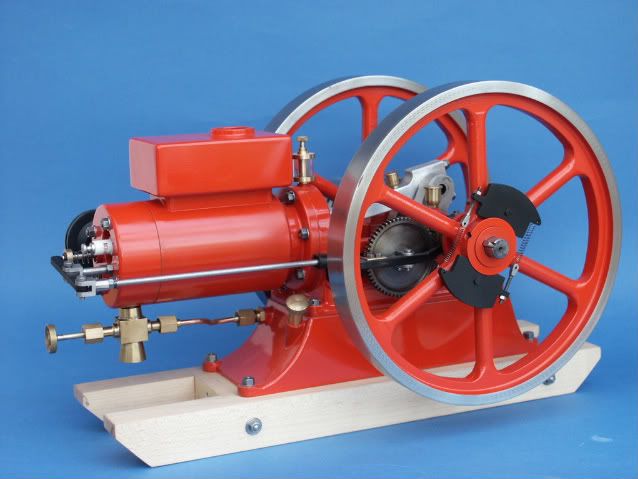
I was not too keen on the look of the engine as I wanted something that looked like it was made from castings. After a few sketches this is what I came up with, mechanically its the same as the "06" but looks a bit different. Flywheels are 7" Stuart spares, Boston Gears all other parts made from bar,plate and sheet.

07-8-1.jpg


07-0-1.jpg


07-10-1.jpg


Jason
 
Well you certainly don't mess around!! nice stuff Jason.... more for me to aspire towards!! ;D
 
very nice work jason. :bow:

is this your first engine?

if so that is amazing workmanship if not we need to see more pictures of you models. ;D

chuck
 
beautiful!, please don't post any more pics! (JJ!)

Giles
 
Thanks for the kind comments

It's had about an hours running before I stripped and painted it, want to get some decent high resolution pics before I run it again, will video it at the same time.

It's my 5th model, will post some of the others.

Jason
 
Jason that looks great, I think you've done a very good job of making an authentic looking engine from bar stock.

can you talk about what you did for an ignition?
 
Ignition is taken care of by a CDI unit from MJN Engineering which is triggered by a hall effect sensor. The magnet for the sensor is carried on a disc fixed to the pully side flywheel and the sensor is on a movable disc next to this so the timing can be advanced/retarded. You can just see the knob for the adjuster above the pully in this pic, the two discs can be seen in the parts picture, they are the brass rings above the piston.

I had intended to hide the ignition within the wooded sledge but will probably keep it separate and connect with a multi socket so I can use the same unit on another engine as well.

The governor works well, the engine fires on every 7th or eight cycle. The carb/timing/governor settings need a bit more playing with as it tends to die out after about 10mins of running but will start again straight away.

There is a bit more about the 06 engine that I based it on here

Jason
 
Jason, that Hit n Miss engine is just gorgeous! I love everything about it. What are the bore and stroke? Also, did you solder the cylinder assembly together? Great looking engine!

Chuck
 
Fantastic - I am new here and this is what I aspire to try to build. Beautiful work!
 
Jason I am a antique engine collector as well as a model engine
enthusiast.

I have one request.
Please don't offer that model for auction in Pennsylvania USA.
It's still a little chilly to be sleeping in the dog house here! ;)

Beautiful work!!!

Rick
 
cfellows said:
What are the bore and stroke? Also, did you solder the cylinder assembly together? Great looking engine!

Chuck

Bore is 1.125" and stroke is 2"

The cylinder/hopper was made in three main parts - water jacket, hopper and the rectangular section that links the two, these were silver soldered as three separate parts and then all joined as one with soft solder.

The cylinder liner is a loose cast iron sleeve that is sealed to the hopper with "O" rings.

Jason
 
Jasonb said:
The cylinder liner is a loose cast iron sleeve that is sealed to the hopper with "O" rings.

Interesting! I would never have thought to use o-rings on the cylinder sleeve.

I have a hit n miss engine I built with a 1" bore and 1.5" stroke. I used an o-ring on the piston, making the aluminum piston about .002 smaller than the bore. Boy does it work great.

Chuck
 
Jason.
I've just started my build of this engine. I like your rectangular hopper idea and will copy that.
What spark plug did you use?
Did you use Viton 0 rings for the piston rings?
Ian
 
Mechanically is is very close to the zero-six so I used a CM-6 plug

99% sure it has two Viton rings, certainly feels like that but would need to pull it apart to be certain.
 
Thanks for that Jason.
So did you make the counter bore for the spark plug deeper than the .450" shown on the drawing so the spark plug end just protrudes into the cylinder bore?
 
looks like I was shooting for 1/2" deep as the counterbore measures 0.498" x 0.750 dia, I'll put that 0.002" down to paint thickness;)

It's not too important to have the end of the plug inside the combustion chamber, I've made hit & miss engines since where the plug is in a completely separate valve block and only connected to teh main cylinder by a small section passage
 
Jason,
I must have had the same impression of the Zero-Six you did, because I gave it bigger flywheels and a different tank too.
Mechanically, mine is as per the plans, but visually I think more pleasing.

IMG_0810.JPG IMG_0813.JPG

The flywheels were "mill whittled" from 1' x 6" discs of cast iron, and the tank is a piece of structural tubing. I used cast iron rings.
I'd seen your red engine in your intro, but never thought it was related to the Zero Six! very nice.
Doug
 

Latest posts

Back
Top