
You are using an out of date browser. It may not display this or other websites correctly.
You should upgrade or use an alternative browser.
You should upgrade or use an alternative browser.
Wyvernish Build
- Thread starter Generatorgus
- Start date


Help Support Home Model Engine Machinist Forum:
This site may earn a commission from merchant affiliate
links, including eBay, Amazon, and others.
rodw
Well-Known Member
- Joined
- Dec 2, 2012
- Messages
- 1,146
- Reaction score
- 340
Gus this is an awesome build. As a kid, we had heaps of stationery engines with cooling tanks. Most of them were plumbed to old 44 gallon drums. I reckon your tank is a good size for the scale of the engine. If it looks like like getting too hot, just "bucket" some water out and add some more cold water.
One difference though, all of our engines were connected by a length of radiator hose to the tanks on both inlet and outlet. I would be a little bit concerned about breaking pipe fittings from vibration with your setup but then your engine is not likely to run 8 hours per day like ours did. I do like the use of unions on the plumbing though!
One difference though, all of our engines were connected by a length of radiator hose to the tanks on both inlet and outlet. I would be a little bit concerned about breaking pipe fittings from vibration with your setup but then your engine is not likely to run 8 hours per day like ours did. I do like the use of unions on the plumbing though!
Rivergypsy
Well-Known Member
- Joined
- Oct 15, 2010
- Messages
- 432
- Reaction score
- 222
Oh, now thats very nice - well done!! :bow:
Generatorgus
Senior Member
- Joined
- Feb 25, 2010
- Messages
- 362
- Reaction score
- 166
Guys, Thanks for the oohs and ahs. It's nice to know people are watching and have taken the time to respond.")
I'm kind of flabergasted that it started up so easily.
I've been a little bummed out for the last couple of days, mostly because it's kind of the end of the trail/tale. I was very somber and apprehensive yesterday morning when I started to reassemble things, my wife even asked me if something was wrong.
When it came time to start flipping the flywheel I was thinking it should run, but will it?
But at the point when I figured out it wasn't getting fuel, I kind of knew it would start if I primed it, everything fealt right, but I was surprised when it fired up immediately.
I'll give the carb some scrutiny when I get over there this morning, maybe it's something simple.
It seems pretty strange that it sucked the fuel up, but never popped or even flooded. The spark plug was dry and not even a hint that the fuel made it into the cylinder.
I never noticed, yesterday, as I was making that video (third attempt) that the intake push rod was just leaning there and not even in place under the rocker before I started.
It ran anyway, like it didn't even need the cam and rocker. I checked the video (second attempt) of the little run I made earlier and the push rod was there and in place while it was running.
If I can't figure out whats wrong with the carb, I may just rig a quicky mixer and give the engine a good shake down run.
I'll keep you posted.
Rod, thanks for your input on the cooling tank. Pretty neat that you had real time experience with them.
I did consider that I could break a something if I plumbed it solid, I just did'nt like the thought of putting hoses somwhere on it. I think if everything is solidly mounted and shaking at the same rate maybe it will be OK. We'll see.
GUS
Mike1
Mike1
Hi Gus.
Your engine starts with a fuel prime, would choking the carb air supply give a richer mix to get the engine running.
Mike.
Your engine starts with a fuel prime, would choking the carb air supply give a richer mix to get the engine running.
Mike.
Generatorgus
Senior Member
- Joined
- Feb 25, 2010
- Messages
- 362
- Reaction score
- 166
OK,
After spending the last eight hours trying every trick I know, and lot of tricks I don't know, I stopped short of doing this.:wall:
Mike, yes I tried choking it several thousand times.
End of work day sitting by the stove, I get a flashback from yesterday morning.
I had to check it out. So, tomorrow morning I'm going to drive into town and visit the custom baseball hat shop. I decided to get one that says "DUMBASS"
When I was installing the exhaust valve cage yesterday morning, I noticed the index mark that told me it was oriented to the exhaust port. I made a mental note to check the already installed intake cage, but evidentally I lost the note.
Yes, it was turned the wrong way. The engine was only getting leak by vacuum. No wonder it wouldn't draw enough fuel. I'm surprised it ran at all.
I was going to wait until tomorrow to correct things but I had to try it.
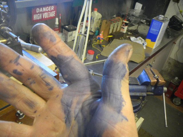
It started up immediately after the fuel reached the needle and actually responded to the throttle, but I accidentally knocked the fuel line off and it quit. My fingers are almost blistered from flywheel flipping and I decided that tomorrow is another day, hopefully a better one.
GUS
After spending the last eight hours trying every trick I know, and lot of tricks I don't know, I stopped short of doing this.:wall:
Mike, yes I tried choking it several thousand times.
End of work day sitting by the stove, I get a flashback from yesterday morning.
I had to check it out. So, tomorrow morning I'm going to drive into town and visit the custom baseball hat shop. I decided to get one that says "DUMBASS"
When I was installing the exhaust valve cage yesterday morning, I noticed the index mark that told me it was oriented to the exhaust port. I made a mental note to check the already installed intake cage, but evidentally I lost the note.
Yes, it was turned the wrong way. The engine was only getting leak by vacuum. No wonder it wouldn't draw enough fuel. I'm surprised it ran at all.
I was going to wait until tomorrow to correct things but I had to try it.
It started up immediately after the fuel reached the needle and actually responded to the throttle, but I accidentally knocked the fuel line off and it quit. My fingers are almost blistered from flywheel flipping and I decided that tomorrow is another day, hopefully a better one.
GUS
Mike1
Mike1
Hi Gus.
Looks like you will have a running engine having found the cause of the initial problem, by the way I thought I would give my Wyvern a run up the other day, and what is normally a good starting engine it just wouldn't start, I was five minutes trying and then noticed the plug lead wasn't connected ( unbelievable ) I can only put it down to the "age thing".
Mike.
vcutajar
Well-Known Member
- Joined
- Nov 6, 2011
- Messages
- 863
- Reaction score
- 169
Gus
I am very happy you figured it out.
I should get a couple of those for myself also.
Vince
I am very happy you figured it out.
So, tomorrow morning I'm going to drive into town and visit the custom baseball hat shop. I decided to get one that says "DUMBASS"

I should get a couple of those for myself also.
Vince
Generatorgus
Senior Member
- Joined
- Feb 25, 2010
- Messages
- 362
- Reaction score
- 166
Yeah Mike, I usually forget to turn the ignition on, or off for all it matters.
A quick update.
I was making progress sorting out the needle setting and just getting to the point that it was starting to smooth out and run, but couldn't quite attain that.
I decided to try fooling around with the ignition timing and got the magnet wheel rubbing on the hall sensor and knocked it out of service.
I did that once on my little H ford engine.
I really don't like the location of the wheel and sensor (the wheel is on the side shaft, just front side of the crankshaft). It's too inaccessable.
I'm going to abandon that location and mount it on the end of the side shaft just behind the crankshaft, where I can access it from the rear.
I have one more sensor on hand, but have ten more on order.
Right now I'm working nights doing maintainance at one of six locations I service for a national restaurant chain.
I can't get my sleep schedule right. As the song goes "the days are foggy and the nights are kind of foggy, too."
I can't seem to muster up any ambition to play.
I can't wait to get back to sleeping nights.
GUS
air-cooled
New Member
- Joined
- Mar 8, 2013
- Messages
- 1
- Reaction score
- 0
Tankonomics:
...
The Blue Mountain (Jacktown) Antique Engine and Tractor Snow Show was at hand.
A dont miss it event for me. A chance to see some daylight and have a good time tossing the bull and wandering thru the outdoor flea market, looking for treasure, and I found a few.
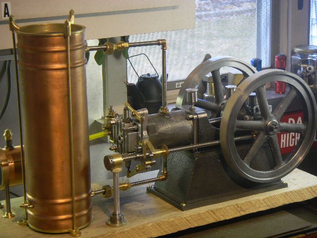
A bit of tooling, a machinist Handbook to name a few, also a copper whats it about 3 ½ dia and 12 or so inches long that may make a cooling tank.
Some sort of expansion chamber maybe?, one end closed off and a ½ npt flange on the other. I asked how much and the guy said $20, I put the thing down and about then I noticed a brass thingy, about maybe 18 long and 1 3/8 dia, about 3/16 wall, one end closed except for a small hole, maybe a chime, which I didnt need but I saw some value as raw material.
Having learned about bundling from a popular TV show, I asked how much for both, his $15 reply surprised me some, I guess he just wanted to sell something. I grabbed the deal and stowed the stuff in my truck.
The brass thing I hung on a coat hook, it gongs nicely, and the copper thing I set in front of the engine and used a couple of Sponge Bob pencils to replicate some piping.
This is my first post here, so I'm not sure if I can post an image link... but do you think your "what's it" (bolded in your post above) might be a water hammer arrestor, the home plumbing type? Some of them have a piston or diaphragm inside, but others are just empty air tanks.

Great work on your engine, by the way.
I started at the beginning and read your whole thread straight through - it's always neat to read how people approach and solve the problems they encounter in projects like this. Thm:- Joined
- May 27, 2010
- Messages
- 2,999
- Reaction score
- 1,171
I'll be following along on your build Gus. It looks like it is going to get interesting
Faraway Singapore Gus also following your pregress.
Singapore Gus.(Rhymes well with GeneratorGUS.)
Generatorgus
Senior Member
- Joined
- Feb 25, 2010
- Messages
- 362
- Reaction score
- 166
Klaus, Thanks, I had a couple of beers while trying to decide what to do with the Hall sensor.
Air Cooled, welcome to the forum. Air hammer arrestor, yes, very possible. Thanks for the comments.
Singapore Gus..Your a natural poet, does that rhyme in Chinese
Air Cooled, welcome to the forum. Air hammer arrestor, yes, very possible. Thanks for the comments.
Singapore Gus..Your a natural poet
, does that rhyme in ChineseGeneratorgus
Senior Member
- Joined
- Feb 25, 2010
- Messages
- 362
- Reaction score
- 166
OK, back to the ignition issue.
Although I hadn’t decided where or how to rig the sensor and magnet yet, I did decide I had to replace the damaged Hall sensor so I needed to wire up the one remaining sensor I had on hand.
I know this has been done on this forum before, but I’m going to post it anyway.
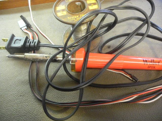
Soldering the fairly tiny sensor leads to the plug harness can be a bit challenging if you haven’t messed around with things like this and up until I built the Lil’ Brother, lamp wire was about the smallest I ever did.
The important thing is to keep the bundle as compact as possible in order to be able to place the sensor where you want it.
Also important is to try not to overheat the sensor in the process.
This go around I decided to try three different lengths for the individual connections using shrink tubing to insulate them.
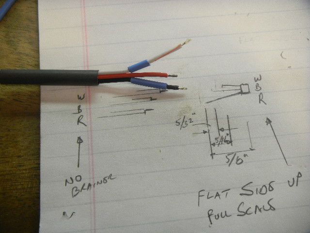
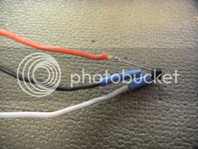
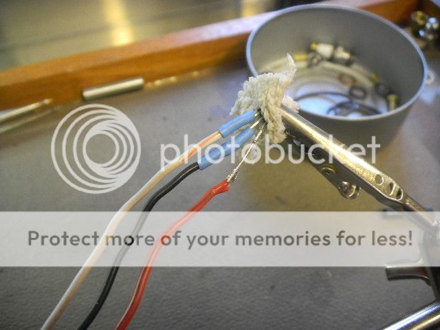
While soldering and heat shrinking the tubing I protected the sensor with a small piece of damp rag and the heat was kept to the bare minimum.
And, of course, all of the tubing should be in place “before” soldering.
The red lead did not need the smaller shrink tube, as the other leads are insulated. The prongs near the sensor seem to be stiff enough to keep them apart.
I thought I only had one sensor but I had two so I wired up a spare.
This rig will slide thru a 7/32” hole.
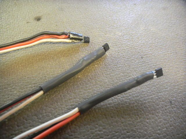
The one on top is one of my first attempts at doing this, I keep it for a spare.
This is the soldering iron I used, for the last three or four I’ve made up, an absolute must in IMHO.
 
After a lot of indecision as to the new location for the sensor, I had a wild thought float across the screen during an one of my afternoon fireside contemplation sessions.
“Why hide the sensor ignition, it didn’t do anything wrong. Other ignition contacts are usually put out in the open where all eyes can see them.”
“ And why not make this one TOTALLY obvious”
Would I dare? You bet!!
I dug thru some bits and pieces and came up with this mock up.
Why not?
Something like a ships engine telegraph.
Yeah, this will be fun.
 
Although I hadn’t decided where or how to rig the sensor and magnet yet, I did decide I had to replace the damaged Hall sensor so I needed to wire up the one remaining sensor I had on hand.
I know this has been done on this forum before, but I’m going to post it anyway.
Soldering the fairly tiny sensor leads to the plug harness can be a bit challenging if you haven’t messed around with things like this and up until I built the Lil’ Brother, lamp wire was about the smallest I ever did.
The important thing is to keep the bundle as compact as possible in order to be able to place the sensor where you want it.
Also important is to try not to overheat the sensor in the process.
This go around I decided to try three different lengths for the individual connections using shrink tubing to insulate them.
While soldering and heat shrinking the tubing I protected the sensor with a small piece of damp rag and the heat was kept to the bare minimum.
And, of course, all of the tubing should be in place “before” soldering.
The red lead did not need the smaller shrink tube, as the other leads are insulated. The prongs near the sensor seem to be stiff enough to keep them apart.
I thought I only had one sensor but I had two so I wired up a spare.
This rig will slide thru a 7/32” hole.
The one on top is one of my first attempts at doing this, I keep it for a spare.
This is the soldering iron I used, for the last three or four I’ve made up, an absolute must in IMHO.
 
After a lot of indecision as to the new location for the sensor, I had a wild thought float across the screen during an one of my afternoon fireside contemplation sessions.
“Why hide the sensor ignition, it didn’t do anything wrong. Other ignition contacts are usually put out in the open where all eyes can see them.”
“ And why not make this one TOTALLY obvious”
Would I dare? You bet!!
I dug thru some bits and pieces and came up with this mock up.
Why not?
Something like a ships engine telegraph.
Yeah, this will be fun.
 
Last edited:
Generatorgus
Senior Member
- Joined
- Feb 25, 2010
- Messages
- 362
- Reaction score
- 166
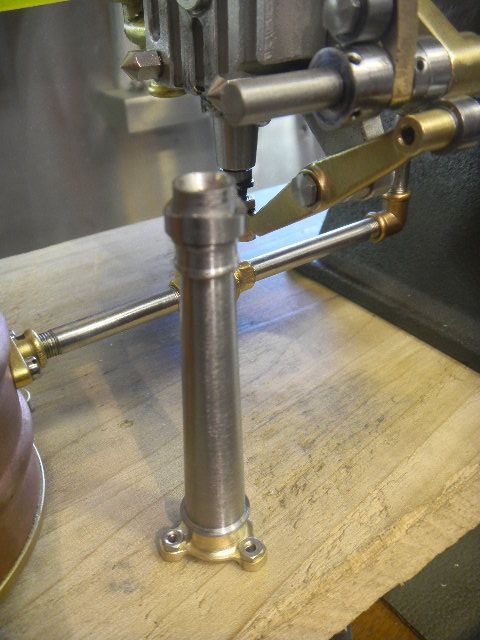
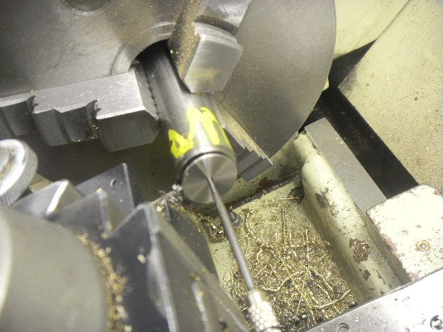
I made a rough sketch of the parts and got right at making the post.
I chose a 5/8SS bar. I originally was going to rough the shape using the 3 jaw then part it off and go to a face plate and offset tailstock for the taper, but I got carried away and forgot to leave a lug on it for the dog to grab.
Now, I had to depend on the compound. There was just enough travel if I made a second ring feature at to top. I had to fool around awhile trying to find the angle but I managed to stumble through.
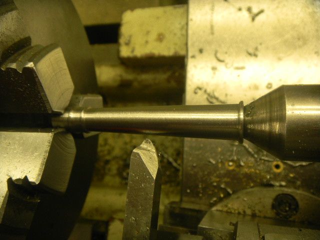
I went on to make a brass base with footies and a loose SS collar to make the mount at the rotor/sensor housing.
Also had a good save? when I knocked the open Dykem container off the counter. I caught it and managed to avoid a much larger cleanup.
The open end of the housing was turned from 1" brass round and a hole for the post drilled and reamed in the bottom. Then ¼ channels milled for the sensor and clamp.
I was intending to use flat head screws for the clamp but figured out that the clamp strap would be almost severed at the at the countersets. I would have to use pan head screws and this would hold the rotor too far away from the sensor.
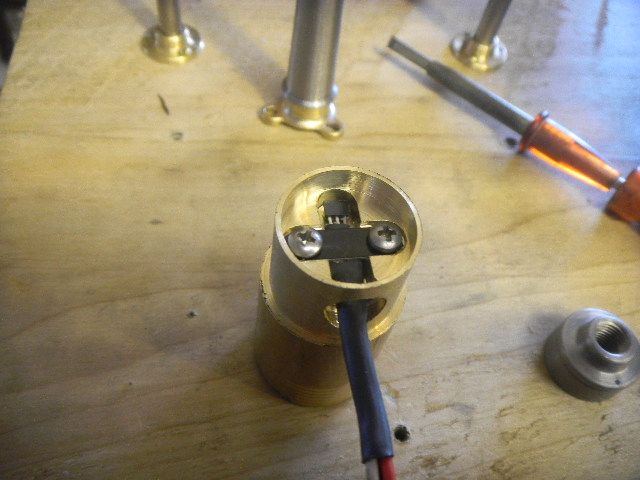
I milled the clamp channel deeper and changed my plan for a flat strap to one with a half round pressed in.
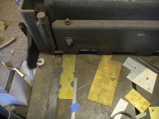
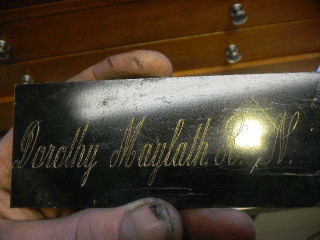
The first clamp now in the jar I sheared a new piece of brass sheet, from a donor trophy plaque.
I have a small box full of botched or practice engraved plaques, donated by a friend. Brass and alum, they come in handy for a number of things.
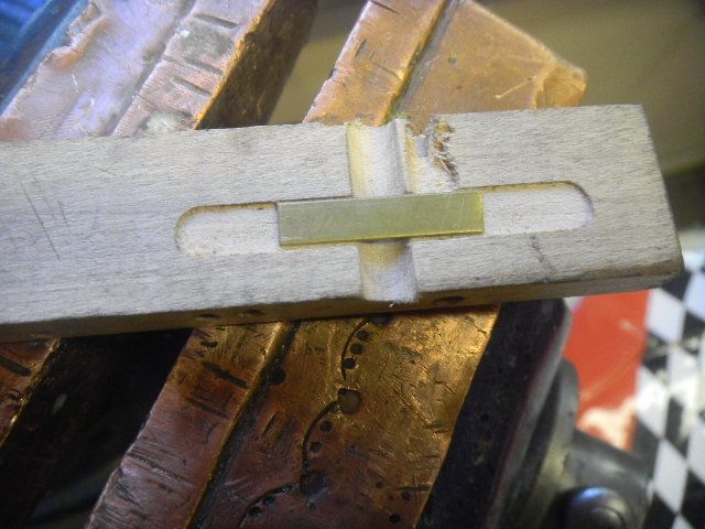
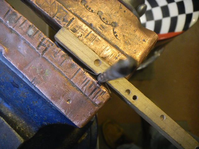
Then made a simple wooden form to press the round in the strap.
The round was then pressed in using the vise and a 3/16 drill bit.
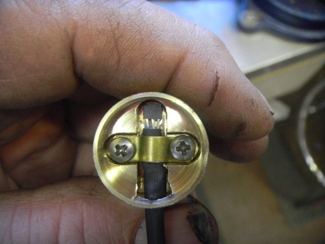
Back in the lathe the housing was parted from the stub end and a face formed then a face plate turned from SS and the housing face drilled and tapped 0-80(smallest hole Ive ever tapped, an accomplishment for me).
The assembly, waiting for Loctite.
The assembly, waiting for Loctite
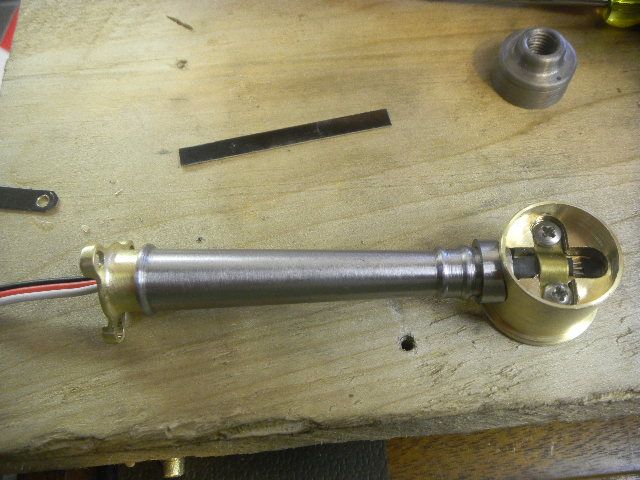
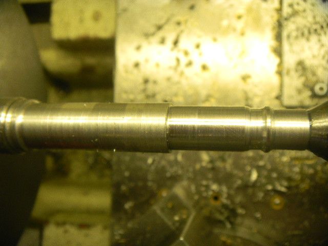
Next, the rotor.
I chose a 5/8SS bar. I originally was going to rough the shape using the 3 jaw then part it off and go to a face plate and offset tailstock for the taper, but I got carried away and forgot to leave a lug on it for the dog to grab.
Now, I had to depend on the compound. There was just enough travel if I made a second ring feature at to top. I had to fool around awhile trying to find the angle but I managed to stumble through.
I went on to make a brass base with footies and a loose SS collar to make the mount at the rotor/sensor housing.
Also had a good save? when I knocked the open Dykem container off the counter. I caught it and managed to avoid a much larger cleanup.
The open end of the housing was turned from 1" brass round and a hole for the post drilled and reamed in the bottom. Then ¼ channels milled for the sensor and clamp.
I was intending to use flat head screws for the clamp but figured out that the clamp strap would be almost severed at the at the countersets. I would have to use pan head screws and this would hold the rotor too far away from the sensor.
I milled the clamp channel deeper and changed my plan for a flat strap to one with a half round pressed in.
The first clamp now in the jar I sheared a new piece of brass sheet, from a donor trophy plaque.
I have a small box full of botched or practice engraved plaques, donated by a friend. Brass and alum, they come in handy for a number of things.
Then made a simple wooden form to press the round in the strap.
The round was then pressed in using the vise and a 3/16 drill bit.
Back in the lathe the housing was parted from the stub end and a face formed then a face plate turned from SS and the housing face drilled and tapped 0-80(smallest hole Ive ever tapped, an accomplishment for me).
The assembly, waiting for Loctite.
The assembly, waiting for Loctite
Next, the rotor.
Dang, Generator Gus----I like your stuff!!! Wish we lived closer to each other!!----Brian
Rivergypsy
Well-Known Member
- Joined
- Oct 15, 2010
- Messages
- 432
- Reaction score
- 222
Very nice work, Gus!
Generatorgus
Senior Member
- Joined
- Feb 25, 2010
- Messages
- 362
- Reaction score
- 166
Guys, thanks for the compliments.
Brian, be careful what you wish for.
I should have stopped playing with this and got more serious about getting the engine running, but I'm having fun, and it's allmost finished.
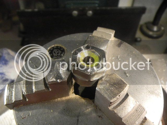
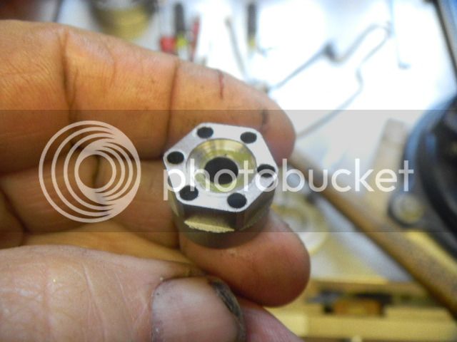
For the rotor I found the cutoff from a hex something? I made, cant remember what it was right now.
Right size, and with a little help it would make an interesting and functional rotor.
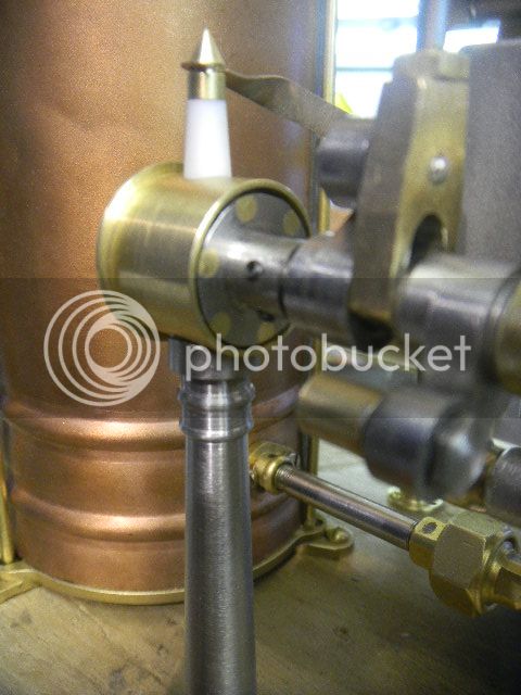
First order was to make it look somewhat armature like, 1/8 holes drilled near the points and 1/8 brass rod Loctited in. Then turned to the proper circumference and a 1/8 button magnet routed in flush on the inside. Sorry forgot to take more pix.
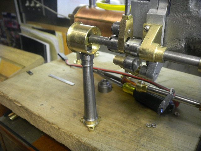
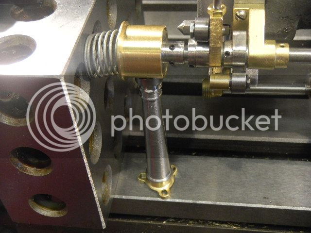
Fairly critical for the glue up was getting the rotor centered in the housing, as up to now, the height was still adjustable via the loose collar.
I came up with this set up. It had to be moveable as the assembly would need to rotate into place, it worked well, but it took a while to get there.
The rotor is centered via the side shaft in a blind hole on the center of the housing.
This is the spring loaded clamping arrangement I came up with.
The timing device may still need to be shimmed in place when it is mounted on the wood base.
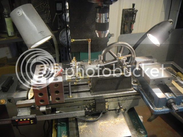
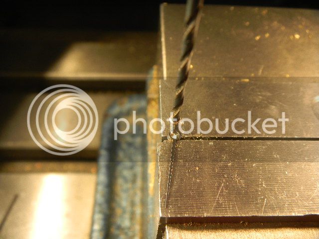
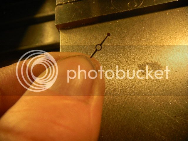
I figured I would need some sort of pointer on the gauge face, so this needle from a Fowler indicator fell victim. I bought a bag of these deemed unrepairable indicators, and they pretty much are, but I needed a needle and it was almost worth the five bucks I paid for them.
I gently drilled out the center insert so it would fit the new mounting screw.
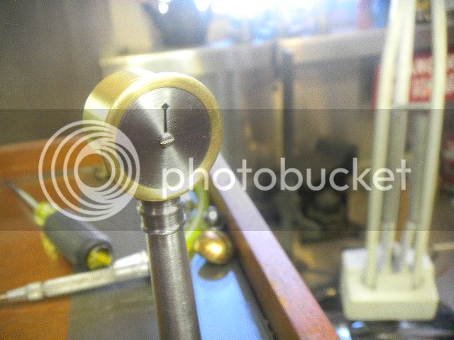
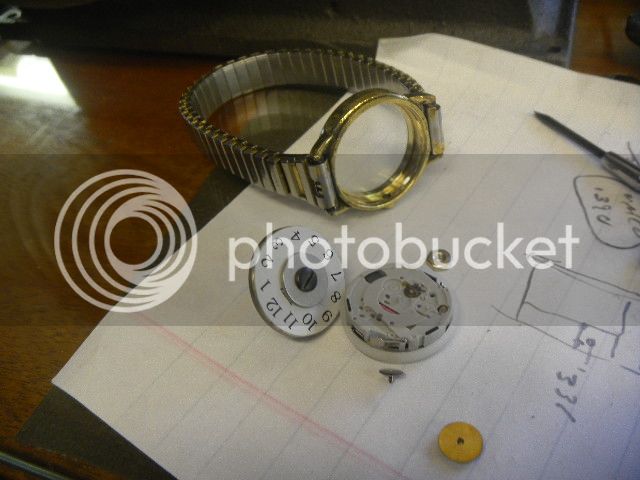
I still needed some kind of numbers to put on the dial. No way I could paint the tiny numbers, and I was getting desperate to find something.
If I already didnt have one foot in Fantasy Land, I put both feet in.
I borrowed a worn out old Timex from my wifes defunct watches collection, shell never miss it, I thought.
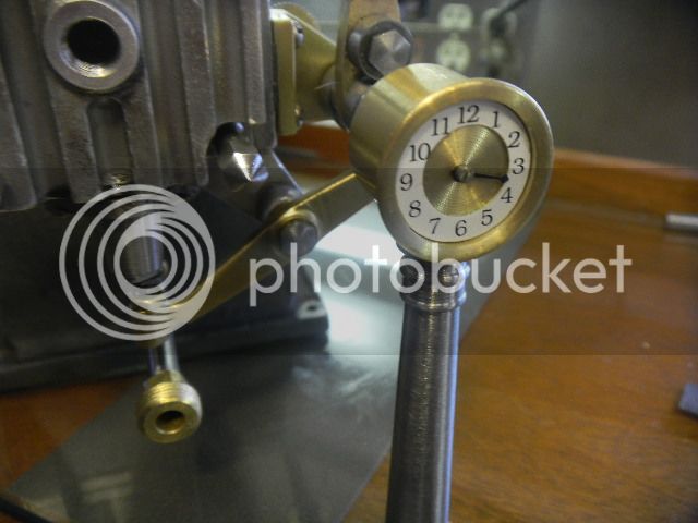
At this point I was, kind of, waiting for a silly white rabbit with a giant pocket watch to come running thru my shop shouting Im Late, Im late.
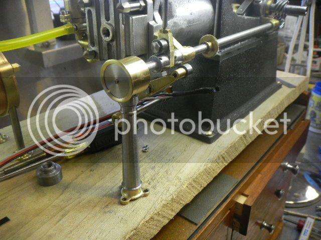
Still needs an adjuster knob.
As a fair trade, gesture I converted the otherwise worthless watch into a Willie Nelson concert collectors piece. Shell love it.
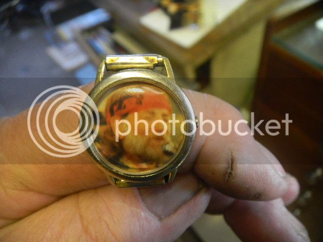
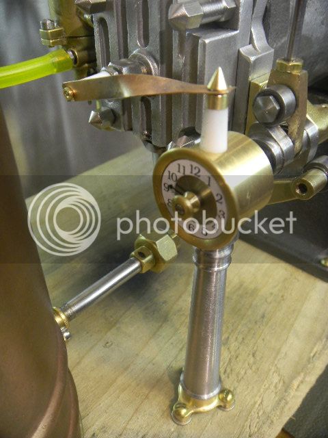
A little brass knob added and I said fairwell to the rabbit and got back to getting the engine running (almost). As a parting shot I added this into the mix.
Not at all fuctional it should get a lot of people thinking.
Brian, be careful what you wish for.
I should have stopped playing with this and got more serious about getting the engine running, but I'm having fun, and it's allmost finished.
For the rotor I found the cutoff from a hex something? I made, cant remember what it was right now.
Right size, and with a little help it would make an interesting and functional rotor.
First order was to make it look somewhat armature like, 1/8 holes drilled near the points and 1/8 brass rod Loctited in. Then turned to the proper circumference and a 1/8 button magnet routed in flush on the inside. Sorry forgot to take more pix.
Fairly critical for the glue up was getting the rotor centered in the housing, as up to now, the height was still adjustable via the loose collar.
I came up with this set up. It had to be moveable as the assembly would need to rotate into place, it worked well, but it took a while to get there.
The rotor is centered via the side shaft in a blind hole on the center of the housing.
This is the spring loaded clamping arrangement I came up with.
The timing device may still need to be shimmed in place when it is mounted on the wood base.
I figured I would need some sort of pointer on the gauge face, so this needle from a Fowler indicator fell victim. I bought a bag of these deemed unrepairable indicators, and they pretty much are, but I needed a needle and it was almost worth the five bucks I paid for them.
I gently drilled out the center insert so it would fit the new mounting screw.
I still needed some kind of numbers to put on the dial. No way I could paint the tiny numbers, and I was getting desperate to find something.
If I already didnt have one foot in Fantasy Land, I put both feet in.
I borrowed a worn out old Timex from my wifes defunct watches collection, shell never miss it, I thought.
At this point I was, kind of, waiting for a silly white rabbit with a giant pocket watch to come running thru my shop shouting Im Late, Im late.
Still needs an adjuster knob.
As a fair trade, gesture I converted the otherwise worthless watch into a Willie Nelson concert collectors piece. Shell love it.
A little brass knob added and I said fairwell to the rabbit and got back to getting the engine running (almost). As a parting shot I added this into the mix.
Not at all fuctional it should get a lot of people thinking.
Similar threads
- Replies
- 0
- Views
- 274
- Replies
- 13
- Views
- 1K