Water Pressure Engine project

Home Model Engine Machinist Forum

Help Support Home Model Engine Machinist Forum:

This site may earn a commission from merchant affiliate links, including eBay, Amazon, and others.
Nice one Steve,

If it can be put right, it was never wrong in the first place, it was just a learning trial that wasn't quite right.

I tend to do a lot of that.

John
 
Make the drawings from the finished project and you will never make a mistake ;D

Impressive engine, I can see why you have been attracted to it.

.
 
Good looking pieces Steve. They seem to fit together well.
Happy B-day, hows it feel to be 45? :D By the way I checked out your main site. Really good pictures there and I'm assuming those marvelous looking kids are your grandchildren? Have fun in ATL.
Tim
 
The Water Engine project is going smoothly as parts begin to pile up and test fittings begin in earnest. Today I tackled the crank shaft using the multi piece method that Bogstandard shared on another thread.

The hot rolled steel crank discs were sized, center drilled, reamed and then cut off using the lathe. 3/16 drill rod was inserted into the two discs, and super glue was used to hold them together. The parts were centered in the mill where the second holes were drilled in both with one shot by moving off center .500 inches to establish a 1 inch cylinder stroke.

Since I had no solder flux on hand, I tried Marv's green loctite to secure the two pieces of drill rod. I also learned that green loctite doesn't like residual cutting oils any better than the red stuff does...(grin). After a quick disassembly, some cleaning and a fresh application of the green stuff, the crank is as stiff as if it had been soldered and Bogster's technique, once the center rod was milled away, gave me a nice crank with next to zero run out. I really like the ease of machining this design offers.

The counter weight lobe profile was chosen for visual effect and might need some adjustment once the engine has been test run. The look was achieved by use of a ball end mill and a bit of patience. It's ready for a final bout of cleaning and polishing, which will have to wait for the moment.


water-engine-crank.jpg


As you'll notice, I've not secured anything yet. All the cylinder pieces fit, so far, but still require a bit of handling as I work. I'll be adding fasteners soon, but I've held off, just in case something bad came up, requiring that I reproduce one of the parts. Basically, it means fewer fiddly steps to get back to where things went bad.

This means the parts in the photos are simply stacked together for test fits and photos. I'm fast approaching the part of the project that will require me to locate and drill a few holes along the center line of the cylinder at its intended elevation. Since I've not yet secured all those loose parts, I was wondering how I'd get an accurate measurement when the time came.

The aluminum base is nicely squared so I placed a machinist square atop the cylinder and squared it against the end of the base. This assured that the centerline is parallel to the base and at the proper elevation. A spot of superglue here and there temporarily secured the parts from moving about. Now I can measure the stack and subtract half the cylinder diameter to determine where the centerline is and where the holes will be needed for installing the crank shaft, as well as the pivot points for the cylinder support arms.

water-engine-squared.jpg


Previous photos made it hard to get an idea of how large this project will be when completed. I place a quarter in the photo to give a better sense of scale. While the engine has a 1 inch stroke and a 13/16 bore, its not really a very large machine.

With a bit of luck, I'm hoping to have the crank shaft installation roughed in tomorrow, so that I can begin location of the steam ports. It's also time to begin buttoning things into single assemblies so they can be secured in their required positions.

Steve
 
Coming along just fine there Steve. You will soon have the basic engine made at the rate you are going.

John
 
John
Thanks for the encouraging words. I'm pretty much working from inside my head (a dark dank and sticky place if ever there was one) on this project, but it is coming along much better than i figured it would. It's abit more stright forward then the Elbow project and a whole lot more forgiving...LOL.


Beginning to look like an Engine instead of just a bunch parts.

water-engine-elevations.jpg


I finally got the cylinder rod shortened, threaded and fitted with a clevis type big end. The clevis was turned on the lathe to get the contours I wanted, including a hemispheric ball cut on the end. It was then moved to the mill where the side flats were cut to fit within the 5/16" gap between the crank web. After tapping the end cap holes the clevis was cut and refitted together for drilling the temporary crank shaft/ indexing holes.

The elevation measurements were spot on, from the last photos showing the square atop the cylinder. This made it easy to locate he needed holes and the crank mounted up right at the level needed. Everything appears to be true and squared.

The base is beginning to take shape after spending a bit of time boring some of the curves into the uprights. Super glue, and a small C clamp held the pair together as they were surface matched with a few quick fly cuts and then bored, using interrupted cuts, as a single unit to make sure all matching surfaces were identical.

The uprights were then fitted to the base and the base marked for boring. The cuts were not too bad considering the amount of metal removed. The front edges are a hint as to the direction things will go. The hard edges are to be rounded and blended to give some approximation of a casting when completed.

Still lots of curves left to cut away from the uprights and plenty of hand file work to come. Tomorrow will see me dealing with soldering and threading numerous 2-56 holes, as I begin to button up a few of the loose ends.

Steve

Steve
 
Well Steve I can almost see that little engine rocking back and forth now.Can't wait to how it turns out.
Tim
 

Well... it's been a few days since I shared the progress I've been making. After a couple of remakes due to silly stuff like forgetting to tighten the vise, I'm suddenly finding myself nearing the "end" of the "roughing in" period. Bits and pieces like the uprights are already receiving a bit of rounding off and are taking on something close to their final look.

The photos below show the little engine at the point where things have gone from parts, to pieces which are now being permanently bolted in place. The uprights are now where they belong and tied down. This allowed me to begin the side arms this afternoon . They are in the very first stages of fabrication and will have soon get bit more time on the curve jig for rounded ends and some tricky tapering. The cylinder base saddle is next to be bolted down and then I can locate the valve ports and

I still have quite a bit of detailing to do as I go along and it looks like lots of cleaning and polishing are in my future.

water-engine-arms.jpg


water-engine-arms-1.jpg


water-engine-arms-2.jpg


water-engine-arms-3.jpg


I'll be happy to answer any questions concerning the "how" if you'll let me know what you want to know. I'm afraid I'm not quite up to speed on this step by step photo thing just yet...LOL

Steve
 
Steve, that engine is starting to look really lucious.

The way you are producing this from a no plans exercise is intriguing.

Have you been doing a bit of copper plating?, if so, maybe the title of bling king is deserved.

John
 
holy smokes steve that is very impressive workmanship indeed :bow: :bow:

i like to see diffrent types/styles of engines and this one is in a league of its own. 8)

i really like the photos and narration of the build.

please keep us posted on the progress ;D

chuck
 
Steve, looks like you're getting there. I think the copper water hammer came out great. We spoke about using the different brass's being an issue but the cylinder looks great with those endcaps on it. Have you used the graphite cord yet? You are making two of these things aren't you? ;) ;)

To everyone else, I got to go over to Cedges place last week and drool over his toys. A great experience! What he is not telling you is he has a massive collection of very unique engines. His wife has to be a very understanding lady. His house is full of engines tastefully displayed.
If any of you are new to the steam/model engine hobby as I then you may also have a difficult time with visualizing scale of his models. So I was truly amazed after seeing how large some of the engines were. His website is great with more detailed explanations of how all these engines work. So I highly recommend checking his site out.
And Bogstandard, I think when this thing is done we may have Bling King race on our hands.
Tim
 
John
Nope... no plating on this one. The red cast on the cylinder is from a bit of soldering I did earlier today to adjust one of the pivot studs I wasn't satisfied with. The flux I use turned things that color, but it comes off fairly easy. The other piece is turned from real copper. The cylinder will polish back to a high shine once I'm done putting finger prints all over it.

You'll always be the Bling Miester to those of us who know and disrespect ya...LOL

Chuck....
Thanks for the kind words. I'm truly enjoying this little project, so I'm taking my time with it. I'm breaking new ground each time I fire up the machines to tear off more metal. A whole lot of what I'm doing is new to me, but I'm learning that I can do it as I go. Thanks for sharing in the fun.

Tim...
So far the brass color thing has been only been of minimal problem. There are some slight variations that I'm getting away with because the pieces are not side by side or they have distinct enough functions that I can claim its a "bearing surface". My poor long suffering wife puts up with me and my toys with few complaints..... as long as I don't ask her to dust either. However, the carpet diamonds are beginning to wear her patience thin...LOL

Steve
 
The project has certainly reached the point where things don't lie. It's either right, or it doesn't fit. So far my mental gymnastics have held up and everything is fitting up quite nicely.

Most of the machining I've done so far has been things we all do, so the "how to" stuff was not very interesting. However tonight's installment is a "how to" that shows Marv's contribution to my arsenal of tools. The rounding table has been getting a work out and so far I can't come up with any changes to make to the littlel devil.

I've learned that it does two functions exceedingly well. It's perfect for rounding off an end and for rounding less than complete circles. These are both done using the first function. The Second talent it has is for cutting tapers or angles on flat stock.

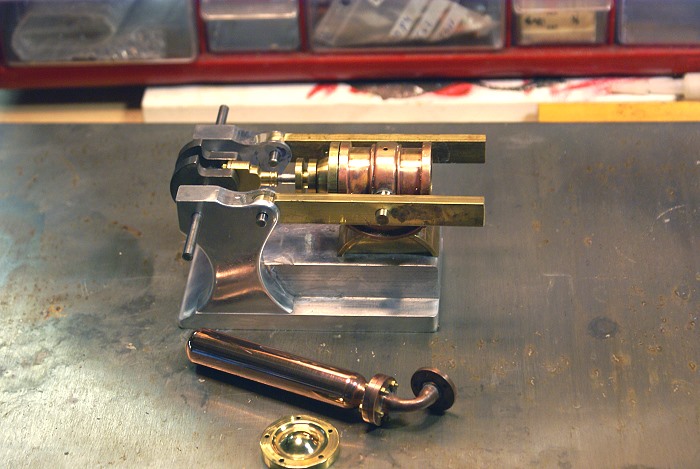
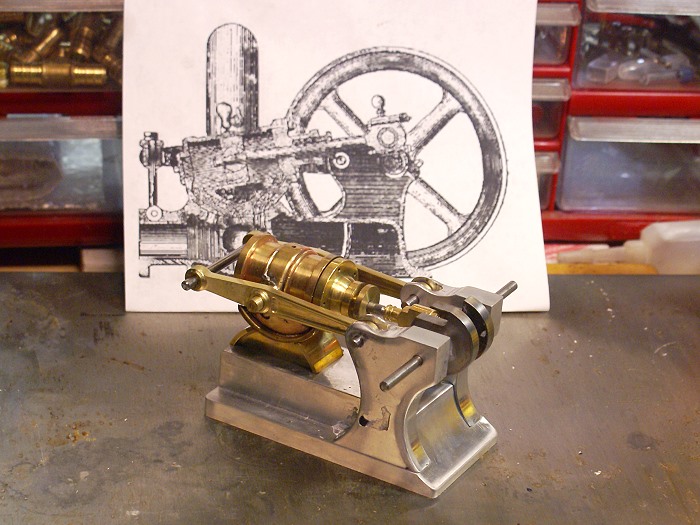
The Water pressure engine utilizes two arms which provide a pivot point for the cylinder, allow tension to be applied to the valve body to form a seal and it allows the cylinder to be swung off the valve for "maintenance". They also hold nearly everything, but the crank shaft, in its proper place.

Since these arms are a "first seen" item, I want them to look good and contribute something more than functionality to the engine overall . That's where Marv's table is proving to be the cats whiskers.

The photos below show these arms in various stages of fabrication and the two functions I've already mentioned.


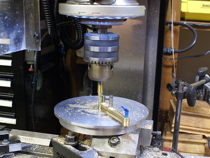
Rounding of the end of the arm is as simple as moving the work piece on the pivot, but real care needs to be taken to keep hands far from the end mill and shallow cuts are a must. you'll note that I've stacked the work pieces and pinned them together with dowel pins. This allows me to cut both pieces at once and it helps assure the pieces are identical. It also allows me to use the same cutter height on both sides without having to reset it. This photos shows the second arm after being cut to roughly its final thickness and the raised section of the rounded end

water-engine-arms-7.jpg


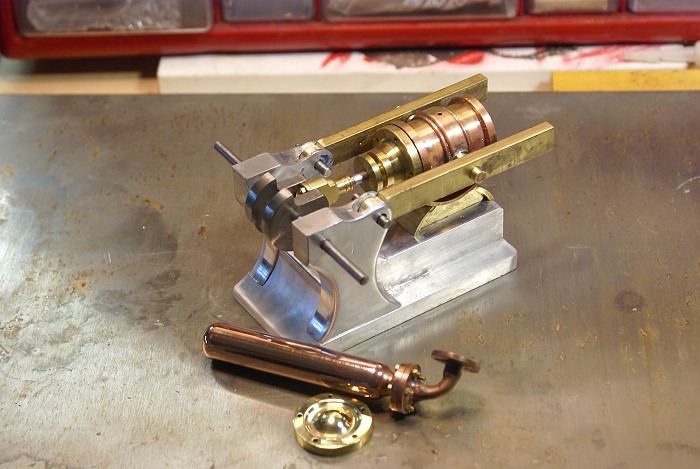
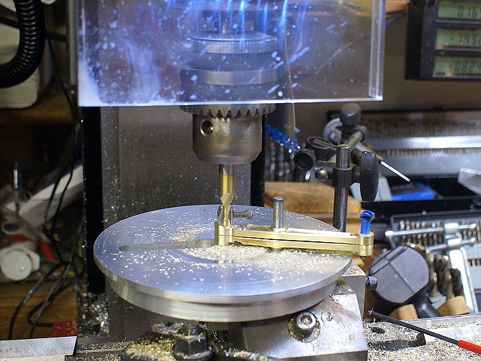
The raised end will be readily visible, so a small ball end mill was used to "step" the profile to add some interest. As you can see, the tool allows for full 360 degree cuts but it also allows for cutting to any point in its arc. I scribed a line at .100 and simply cut until the line was reached to create a "neck".

water-engine-arms-9.jpg


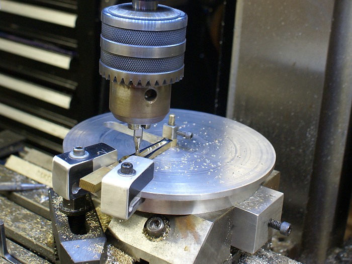
The next photos are from a bit earlier in the process and show the other nice function this tool can give you. I wanted the arms to look a bit more structural than if they had been left with flat surfaces. I had already cut the outside taper on the mill by resting the small dowel pin on the vise top and then adjusting emd mill to "blend" at the " neck line" of the round end. I then adjusted the angle to let he end mill escape its cut at the center of the middle hole.

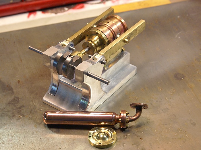
Now I wanted to duplicate this line .075 from the edges of the arm. After scribing the lines, I swept the edge of the work piece with the ball end mill to align the arm along the cut path. Then the end mill was moved to the interior of the line and the cut was made from front to back. The second angle was then set up the same way, by sweeping the opposite side. The rest was just cutting away the center metal. I cut each arm singly only because I had just messed up the small bushing I'd been using to index the center hole. This process could have been done with the arms pinned together, just as easily, if not more so.

water-engine-arms-6.jpg


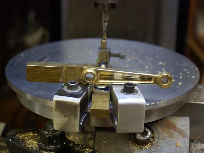
Here is the results of the cut, so far.

water-engine-arms-5.jpg


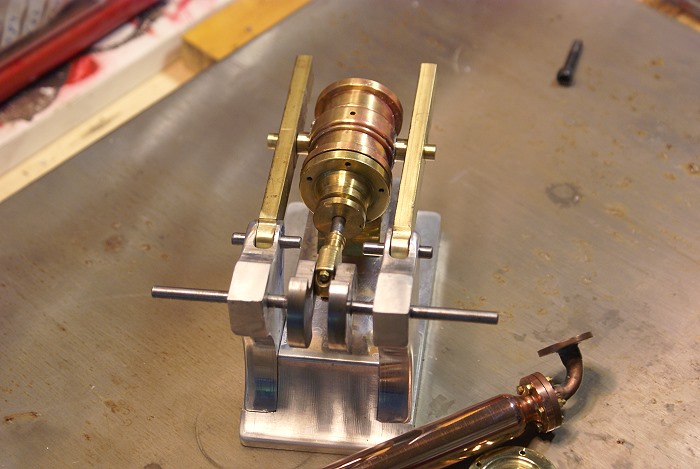
Here are the arms being test fitted after machining , but before they are polished. I will be cutting the web on the short ends of the arms tomorrow, It's definitely not something to do when you are tired or distracted. A fresh start in the morning, after a good night's sleep is what the doctor ordered tonight.

water-engine-arms-10.jpg


Marv... I really do love this tool...LOL

Steve


Lovely stuff Steve, isn't it a lovely feeling when you get used to a new fixture?, and it starts to allow you to do more and more.

From your previous post, about the carpets. My wife is now so fed up with sparkly carpets, she has laid the law down, and we are getting rid of them, and putting down decorative ceramic instead. It will be easier on her as she will only have to get down on hands and knees to scrub them clean, rather than vacuum, as she does at the moment. I will never understand a womans reasoning.

John
 
John
Three years ago I wasn't even sure I'd enjoy this hobby. I bought the machines knowing I might wind up selling them at a loss if I didn't like doing it, but at least my curiosity would have been settled.

When I found this board I was still struggling with rudimentary things and the mill was not any sort of friend. I jumped in way over my head more than once and fought off the alligators all the way to the edge of the swamp. Posts like yours have cleared up a lot of mysteries and given me ideas that I'd have gotten no other way. Don't get me wrong... I still struggle with things and do a lot of it the hard way, but each project gives me a bit more knowledge and the courage to use it.

Will this little engine run?... who knows... its the journey that I'm enjoying, not the destination. I get just as much joy from a well made tool as I do the engines I so much want to build. Having one perform the yeoman's duty that this one has is a very satisfying thing that I can enjoy each time I use it in a new way.

I'll never figure women out. If I did I'd just wonder all the more as to why she chose me...LOL. Mine is pretty unique. She'd rather have a good power tool to add to her growing collection than the best offering at Victoria's Secret. She asked for a chainsaw for Christmas, a Makita cordless drill for mothers day and this weekend she decided she wanted a back pack style leaf blower.... so off to Home Depot we went. I'm quite happy to let her use my tools, but we still have a fair number of his and hers tools laying about. Hell... you just don't find em like her...LOL.

Steve
 
Hi Steve... have you any drawing of your nice table?
TY Paolo
 
Steve those arms really set it off. I bet if you glass bead you would not know they weren't cast.
Tim
 
Carefully tiptoeing in here Steve but your "Tuit" list should really include some proper cutter holders for the milling cutters rather than the drill chuck. It would be heartbreaking to see a cutter "Walking" out of the chuck. On my modelers type Auto Lock I made some adaptors for the small plain shank cutters with a grubscrew to lock into the notch. Regards Ian.
 
Ian
You caught me being a little bit lazy. I have an ER 40 collet set but I was switching bits so quickly to make a number of different light cuts that I left the drill chuck in for convenience. I just looked back across the project photos and it seems as if the drill chuck is all that was being used. Trust me... having had end mills take a walkabout I know what you mean.

I think one of my next purchases is going to be a set of R8 Collets. I have really come to like the ease of use with the R8 setup on this machine.... much nicer than the MT3 on the old X2 machine.

Tim
I'm considering several ideas for finishing the webs. Glass beading is one of them. Rounding the edges has already begun to give it some of that cast look.

Paolo
I don't have any drawings, but I'll be quite happy to take it apart and shoot some photos. It's really a pretty simple design with few parts and only one or two "critical" dimensions. It's basically the same as the one Marv shared in an earlier post, but I used a round top instead of the rectangular one he used. It's definitely worth the time and metal to build.

Steve
 
Back
Top