Water Pressure Engine project

Home Model Engine Machinist Forum

Help Support Home Model Engine Machinist Forum:

This site may earn a commission from merchant affiliate links, including eBay, Amazon, and others.
Thanks a lot Steve It would be nice... :bow:
Paolo
 
Today I took things easy, but I got a bit done to the engine and made a couple of choices in direction.

The photo below shows the engine after the machining was completed on the side arms. The webs have been cut and contoured, with some preliminary polishing begun. I'm pleased with the visual aspect they lend to the machines.

I hadn't tried a flywheel on the engine until last night, just before calling it a night. I fitted a 4 ich commercial flywheel on the crank shaft and it just didn't look right. The engine looked too elongated and, for lack of a better description, "spidery". Definitely not what I was looking for. I had a 5 inch flywheel on the shelf, so I slid it onto the shaft. The engine pretty much told me that the larger flywheel was where we'd be going . The wheel falls along the same line as the old wood cut I've been working from.

Having had a bit of success in building a multi piece flywheel for the Elbow engine project, I'll probably be doing the same for this one. I spoke with Wes (Powderkeg) this evening and his schedule is pretty heavily booked for now, so if he has a 5 inch pattern to cast, I'll possibly swap mine out for one of his curved spoke designs at some later date. No rush, Wes... I'm not wanting the project to end right away and besides, I need the practice....LOL.

Enough jaw boning... here's the photo showing the test fitting of the flywheel and the "finished" side arms.

Steve

water-engine-arms-11.jpg
 
After an extended delay to get Bogster's finger engine challenge inspired projects put to bed, I'm finally back on the Water engine project again. The break gave me a chance to study the project a bit and to make sure all was as it should be. The components are now finding their final homes and getting bolted down. The plumbing and porting are both making progress and so far, all is going well. The photo below shows the engine during a test fitting of the air chamber. The red marks which will be used to locate the upper cylinder ports.

water-engine-ports-full.jpg


Here is a detail shot of the freshly installed copper plumbing. These were press fit for a nice tight seal, since solder was not an option. The holes were drilled at different elevations so that they would not interfere with each other.

water-engine-plumbing.jpg


This photo shows the lower ports along with a detailed look at how the lower saddle was attached. The original idea was to bolt it from the bottom, but this would have collided with the plumbing ports. Just another example of how a project like this will sometimes dictate its own evolutionary requirements. There have been surprisingly few instances where such changes were required for this engine, but I'm "listening" to it as I go and I'm not so stuck to any idea that I am unwilling to change things as the project tells me it's needed.

water-engine-ports1.jpg


This engine has a neat ability to allow the cylinder to swing away for maintenance. The two small red marks in the upper valve body are there to locate the two ports. This will be the next step, followed by the studs in the cylinder ends. Other small details yet to be done include bolt up flanges for the copper lines, the tension bar to hold the cylinder down, bronze bearing blocks for the crankshaft and a few decorative details as yet undetermined.

water-engine-parked.jpg


Hopefully I can get a few days worth of work in on the project and begin buttoning things up. I'm currently debating on how I'll go with the flywheels. The one shown is used only as a mock up to give me a visual idea of how the finished project will look.

Steve

 
That's really an interesting and unique engine, Cedge. It'll be quite a nice piece when finished.

Cheers,

BW
 
Thank you Bob. That is the goal, as I add to the collection. I've even begun considering weeding out some of the casting engines from the group, as I become able to build my own versions. The ideal would be a whole collection of unique, built from stock, engines, but I'd really be hard put to let go of some of the casting engines I've managed to acquire.

Now, I've got to get this one to the smoke testing phase....(grin)

Steve
 
Steve,

You have really amazed me with this build, from some crappy old line drawings and a few pics, you have managed to get an engine that replicates the original almost perfectly.
It should be a fine addition to your collection.

John
 
Thanks John
Half the challenge has been the lack of any drawings, but it's also been half the fun. I've learned more about how steam engines were designed from this project than any so far. I'm not nearly as intimidated by the prospect of taking on more complicated builds now. I'll have to admit it's turning out much closer to the original than I expected it to. It has also raised the bar on my own expectations for myself.

Thanks for the encouragement....it's kept me going when the corners I'd boxed myself into got a wee bit tight. It's pretty hard to shelve a project when you have a cheering section...LOL

Steve

 
The words "museum quality" come to mind when I look at this marvel. You are an extremely patient man!
 
Castings are neat too. The texture is pretty hard to reproduce from bar, althogh I bet there are ways. I've almost accomplished it accidentally! LOL

I sure wish you'd put out a set of drawings for this one. It's awfully intriguing.

Cheers,

BW
 
Bob
Drawings are not my strong suit, but once the engine is running and proven, I'll be looking into the idea. I'm great at modeling in 3d, but frankly, I'm pretty lousy when it comes to translating that to 2d build drawings anyone could read or even trust. I'd probably have to recruit Tim to even come close.

Steve
 
Cedge said:
I'd probably have to recruit Tim to even come close.

Steve

I'm always up for that. And I would love to have this beauty on my list of to-do's.
 
It seems like these posts get further and further between, but the small stuff seems to take more time as the project progresses. A lot has been accomplished since the last post, although none of it is of the large or dramatic variety. A good bit of detail work is yet to come, but the photos below will share where things are up to now.

One of the items I was almost dreading was drilling the upper cylinder ports. The drill would have to cross a rather long solder joint and the potential for a broken drill bit was not something I was thrilled about.

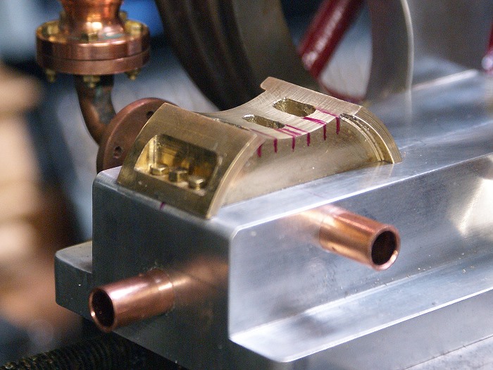
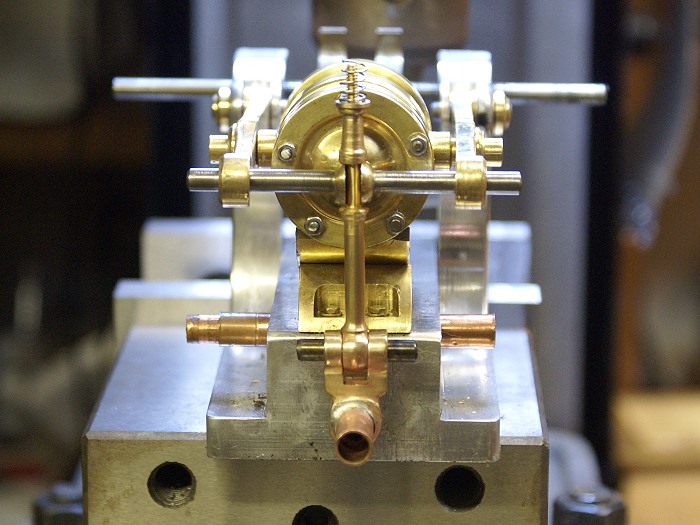
I began by locating and drilling the holes beneath the cylinder. This was done by marking the existing ports on the side of the lower valve saddle and rocking the the cylinder to pin point the maximum travel. At that point one of the ports would be located over the bottom center port. When marked and rotated the opposite direction, the the other cylinder port could be marked as it also matched up to the center bottom port. Once marked, both holes could be easily centered and drilled. It was quite interesting to let the little engine show me where they would need to go.

water-engine-details2.jpg


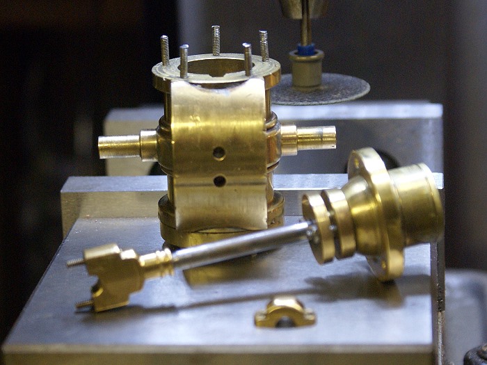
The ports then needed to travel out to the ends of the cylinders. This is where the rectal tension factor increased. The high angle of attack the drill bit would have to follow across the soldered gap between the cylinder and the saddle had me sweating a bit. I began by milling a small flat perpendicular to the line of travel. Nothing hard there since the drill angle had already been established. All that the flat required was normal milling.

A quick shot with the center drill and it was time to make the holes that would tie the ports together. Fortunately the operation was a complete success, but I was holding my breath until the solder chips from the joints gave over to nice fresh brass again.

This photo also shows the end cap studs I chose to use. These are screwed into 2-56 tpi hand tapped blind holes which stop just shy of exiting the flanges by .010 in. The studs are commercial threaded rod I had on hand. A tedious operation but one that went quite smoothly, with no broken taps.

water-engine-details1.jpg


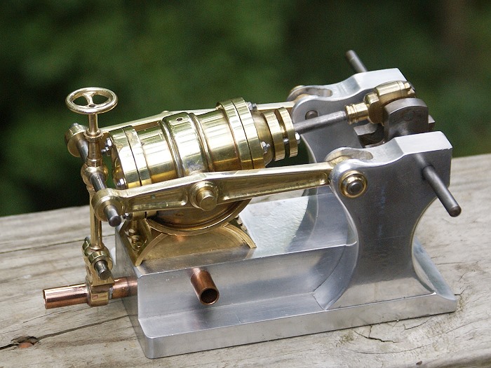
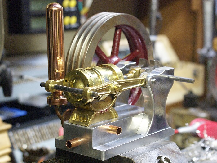
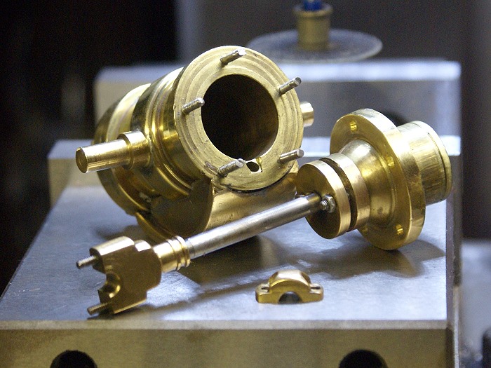
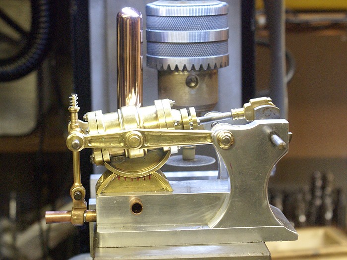
The next item needing attention was the rear tension mechanism that serves to hold the rear of the cylinder down when the engine is running. It also allows access to the saddle for lubrication and such.

The lower clevis was machined as one piece, using the mill and Marv's marvelous rounding table idea. ...did I really pun that? The transverse holes allowed rounding at 90° angle to each other. This would have been difficult, if not impossible, without it. The vertical stem was also turned as one piece using the ever popular ball turning tool. The flats were milled and drilled on the milling machine and the 4-40 upper thread was hand cut using a 4-40 die.

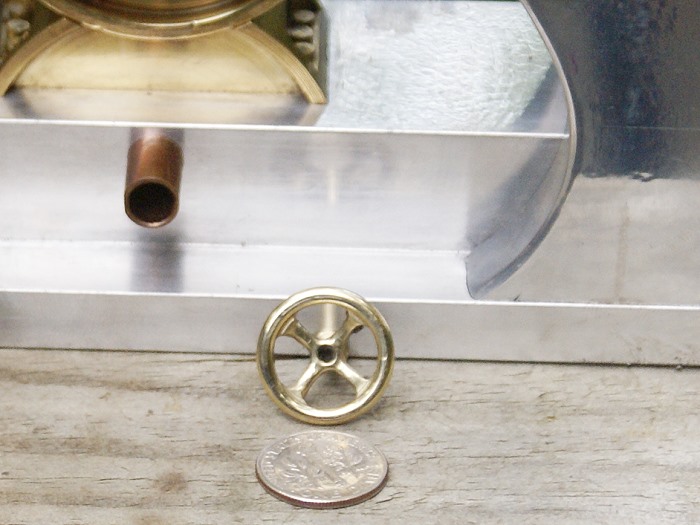
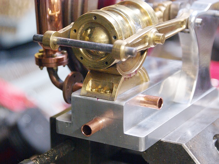
The ball on the cross bar was soldered in place and then the slot was milled out, leaving the piece solid enough to do its job. The piece above the cross bar serves as a spacing bezel to give the soon to be made hand wheel clearance above the oscillating cylinder end.
water-engine-details3.jpg


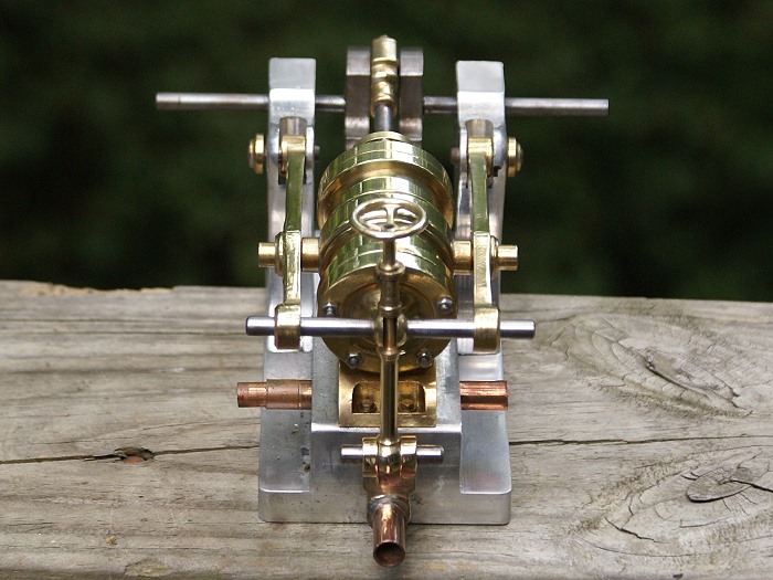
Here is another view of the tie down assembly. The cross bar will eventually be held in lateral position by a pair of 2-56 hex head cap screws through the tops of the pivot arm ends. The lower clevis was soldered in position after being fitted with an extension to the copper pipe.

water-engine-details4.jpg


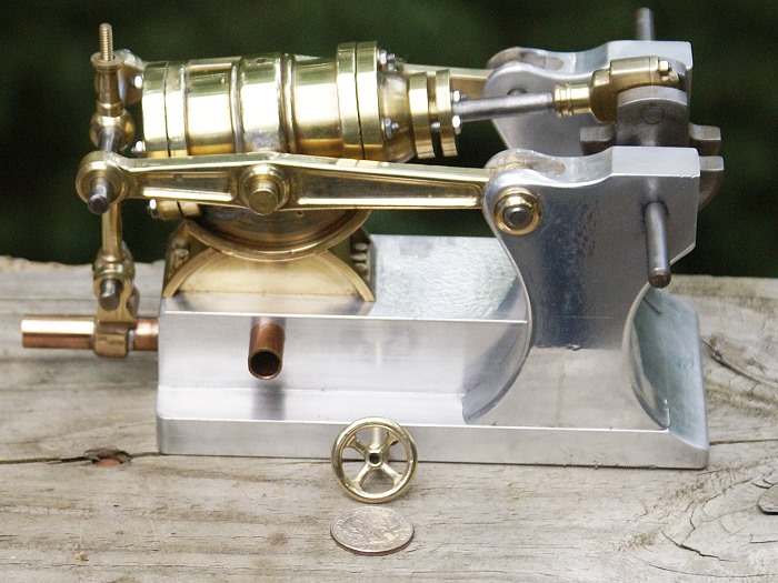
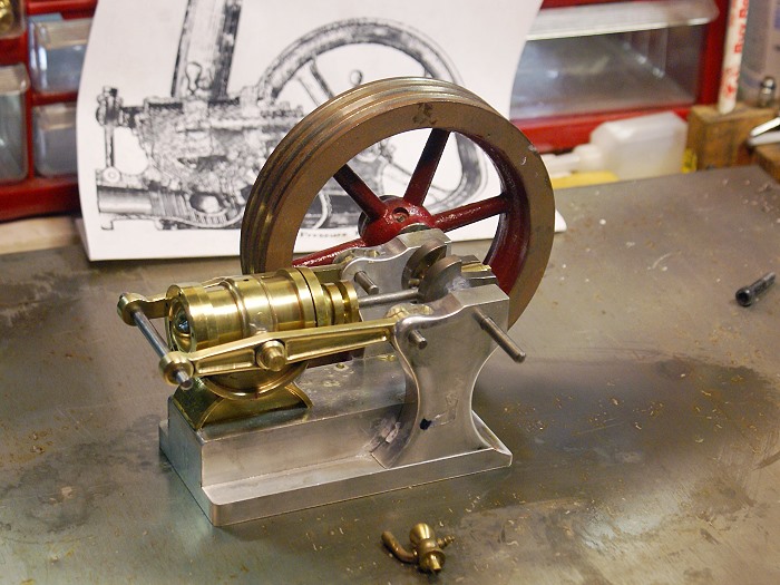
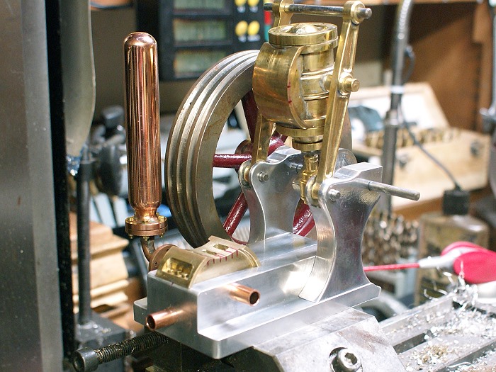
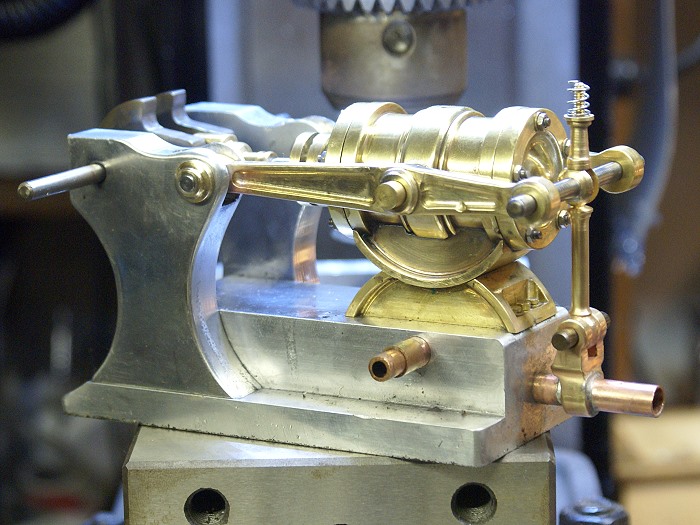
The photo below shows the assembled engine components at the present time. Small things like the brass caps on the pivot arm pins will add a bit of additional visual detail to enjoy. The crank shaft will soon have brass or bronze pillow blocks and some type of oilers are planned for the motion points of the little motor.

water-engine-details5.jpg


Still a quite bit of detailing left to do, but the project is nearing completion. I've already test run the engine on air and it is sewing machine smooth. I can't wait to see it running again once the large flywheel(s) is/are installed.

Steve

 
Take as long as you like Steve, standing here in awe.

Good things come to those who wait, and we sure are waiting with baited breath on this one.
Wonderful workmanship, even in the rough. I dread to think what it will look like when you have a cleanup session on it. Awesome.

John
 
Thanks guys. I'm not quite sure it deserves anything like awe but, I'm quite pleased that it's being well received. I'm going to miss working on this one, once it's done, but the next project engine has already begun to occupy my mind. Now to find enough space to display them as I get them built.

Steve

 
I've been waiting to see more pictures of this one Steve, I love the shapes and all those curves ;D

Can't wait to see the finished article :) (still no need to rush though ;) )


Ralph.
 
Wow! This is coming together nicely. Wonderful detailing on the parts. Looks like something you would find in Jules Verne novel! 20,000 leagues under the sea! ;D
 
Summer seems to mean less time, rather than more, to get into the shop and tinker. I finally got a bit of uninterrupted time last night and before I knew it, the clock was showing almost 4:00 am. Talk about getting lost in your work, this short installment was both intricate and entertaining.... not to mention, very instructive.

The rear hold down on the engine needed a means to secure it when I last posted, so I took on the challenge of making one that would visually fit the engine. It took a few days for me to decide on what I wanted it to look like and several ideas were considered and rejected. The results of the effort can be seen below.

The hand wheel idea won out, but it couldn't be a normal "flat plane" design. It had to clear the operating arc of the cylinder, mate to the previously made bezel and look old fashioned. I decided to try for a "dish" with spokes. Having never milled a spoked flywheel, choosing to do something less than the size of a dime seemed just about par for "never do it the easy way, Steve". If it's not a challenge, then it's not much fun.

hand-wheel1.jpg


A dime is the smallest US coin and measures 17.85 mm. The hand wheel measures 1/2 inch in diameter which got to feeling a wee bit tight as things progressed. The contour was turned on the lathe and then moved to my little homemade indexing table for milling. I recently bought a set of carbide end mills which included a 1/16 inch 4 flute cutter. This is what was used to cut out the spokes to .05 width. The edges were hand filed to round them off and bring them down to proper scale.

hand-wheel2.jpg


This photo of the rear end view gave me some satisfaction. Everything is falling in place with good symmetry. The visual look is still headed in the right direction and Steve is a very happy camper. Some of you might notice the spring in the previous photos is missing. It proved to be less than properly functional, so it was eliminated.

hand-wheel3.jpg


Here is the side view with the cylinder held down in place. The hand wheel was easier than I'd expected, but it did manage to keep me on my toes, working in such a confined space. However, I'll be a lot less apprehensive when it comes time to try making a one piece spoked flywheel. That should feel like I'm working with huge amounts of room.

hand-wheel4.jpg


Steve
 
Steve, that looks great.Glad to see all the hard work and long nights are paying off. I think this engine will fit you collection well.
Actually you may be diminishing the value of your investment on bought engines when you start adding things like this to your collection ;D
Tim
Back to work.
 
Back
Top