Water Pressure Engine project

Home Model Engine Machinist Forum

Help Support Home Model Engine Machinist Forum:

This site may earn a commission from merchant affiliate links, including eBay, Amazon, and others.

Cedge

Well-Known Member
Joined
Jul 12, 2007
Messages
1,730
Reaction score
29
I mentioned this project had begun on another thread. I was determined to get shots of the engine as it progressed but I still got more engrossed in cutting metal than in taking photos. It finally dawned on me that the camera was sitting there for more than the irritation factor it created by being in the way...LOL.

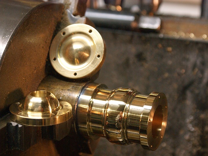
The engine is an odd style of oscillator that rocks in a radius instead of up against a flat steam chest surface. The cylinder will pivot within this radius to allow port switching as the crank moves the cylinder rod in a circular motion.

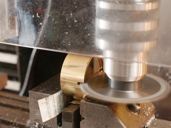
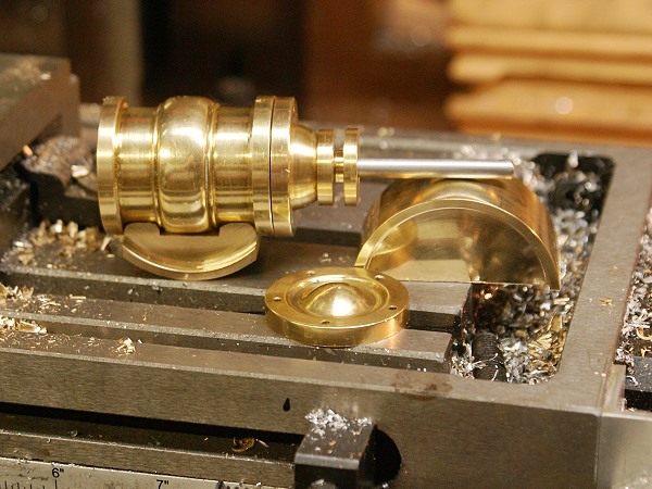
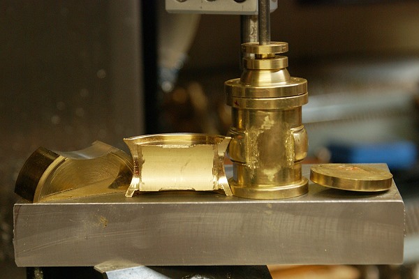
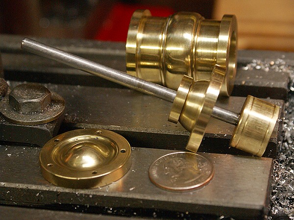
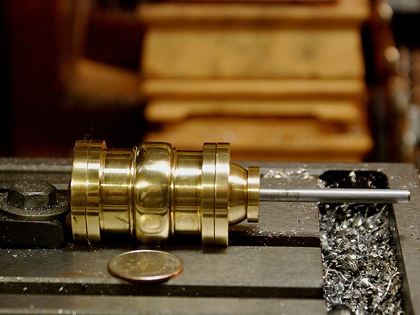
Below is the cylinder prior to adding the pivot points and the end caps, one of which will soon be fitted as the stuffing box. The end cap contours were cut with a ball cutting tool and a hand made gravier. The Cylinder contours were cut using a series of triangular and bastard files. Everything was then sanded with papers from 100 to 2500 grit and finished off with metal polish. The bore is 13/16" and the stroke is 1 inch on this engine. 13/16 was Hobson's choice once the boring bar chattered its way past the 3/4" mark. Honing the cylinder was done using 600 and 2500 sand paper and a piece of wooden dowel rod.

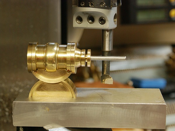
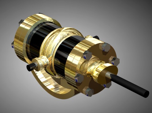
Below you'll find my photos of the engine I'm working form, my 3d rendering and the parts I'm making so far.
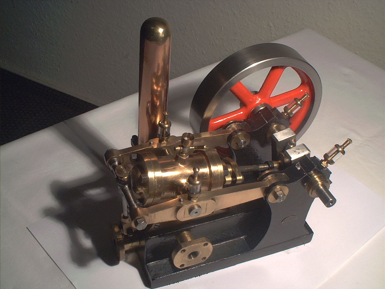
sam023.jpg


water-engine-cylinder-1.jpg


water-engine-cylinder-2.jpg
 
Lookin good Steve. I still have a had time pictureing how it works, so we will need a video when finished. I wish I could get my cad models that shiny, Mine have no reflection like that. Mabey I need some Brasso on my screen :big: Great work!
 
Lookin' 'groovy' Steve.

Once you start, the pull of the workshop gets greater and greater, so expect a lot of sleepless nights trying to figure how to make the bits.

This project is definitely a 'watcher'

John
 
Wow that's a cool looking engine! Where did you find the thing? What does the vertical chamber do?

I am somehow reminded of the "water hammer" effect on this engine.

Definitely need a lot more pics to understand it. I am assuming the little radiused part underneath the cylinder in your 3D render is what you refer to as replacing the steam chest? As it rocks it is presumably opening and closing the appropriate passages?

Very intriguing, and an extremely good looking engine as well. I see why you were attracted to it.

Best,

BW
 
Bob
Your guess was spot on. The engine was designed to run on water, steam or air. The column was there to absorb shock should the water pressure surge... ie. Water Hammer. The radius does indeed serve as the steam chest, switching the ports as the engine rocks in the saddle.

I often get emails offering to sell me engines. This was one of those offers. The owner wanted far more than I wanted to pay for it, but the photos were good enough that I figured I could dig out enough information to try to build one. My collecting has centered around finding engines with unique or unusual mechanical functions, so this one looked like it would fit right in.

Steve
 
Bob
Once I know what I've got as a finished engine, I might have to coerce Tim to model it out in Solid Works. Seems that his 3d software might not do all the fancy reflections and shadows that mine will, but his will pop out nice detailed build plans from the 3d image. That, I envy....LOL.

Until I manage to stumble through the "prototype", I won't actually know what the final dimensions really are.

Steve
 
FWIW, I'd be happy to draw up plans in Rhino3D too!

Best,

BW
 
I've not been able to stay on the project as much as I'd like, but some progress is being made. The photos below show the first test fitting of the cylinder components as a full assembly. Nothing is bolted together yet but the alignments are looking good. I've also begun the radius bearing for the cylinder side, but it's not ready for photos just yet.

For those interested, the bore lapping is done and the rod and piston are sliding freely and will create enough of a seal to pick up the end cap, when the piston is moved. I'm not yet sure if I'll need to go with a fully working stuffing box, but I've left plenty of room to do so, should it be required.

I'm learning many new things on this project, all the while taking my time and having some fun. I forget who's tag line says "one perfect part at a time", but it's become a bit of a mantra as I work. I kind of like being able to zone in and pay attention to only one part until it is just like I want it, before mentally dealing with the next one. I'm trying to keep the overall context of the project from dominating my head until I need to look at it as a whole. It's a much more satisfying process so far.

Steve

water-engine-cylinder-3-parts.jpg


water-engine-cylinder-3.jpg
 
Looks like you are getting great finishes there Steve:eek:) I can't wait to see how this one comes together.

Wes
 
Wes
The preliminary polishing was done to remove most of the tool marks. The photos show the parts after being handled quite a bit, so they are pretty dull at the moment. I'm hoping this one will nearly glow when the final clean up is finished. Black lacquer and brass bright work should keep me polishing and dusting the thing for years to come...LOL Thanks for the kind words. I think it's gonna look downright awesome with your flywheels installed.

Steve
 
Beautiful work Steve, just what I expected from you.

If I could make a suggestion on your build, put the stuffing gland in before going any further. They are needed on double acting engines. As you said in your PM, the graphited string is really nice to play with, but the better half doesn't like black all over the house.

Don't forget to clean the swarf off when it reaches the vice top.

John
 
Steve, It's looking good so far. So what is next? And what size are the srews for the end caps? Wish you the best of luck tapping thoses.
Tim
 
Tim
Those will be hand tapped at 2-56...in blind holes, so the wish for luck is much appreciated. I've hand tapped a lot of 2-56 in the past, so I'm not quite as nervous as i would have once been. I use a nice new sharp tap and lots of holding my breath....LOL. It's not too bad in brass, but this stuff doesn't behave like normal brass, so the odds of success remains to be seen.

Steve
 
Make things easy for yourself. Use a #49 tap drill instead of the recommended #50. A #49 will give you 56% DOT which is plenty for this application and will provide less resistance to the cutting action of the tap.
 

I made a bit more progress today and learned quite a bit in the process. Getting to watch a boring bar as it cuts will let you see what works in real time. Feed too slow and the bar gets bored and begins to chatter. I found that a nice even 600 RPM on the mill and some surprisingly fast feed rate was what the metal and boring bar were wanting... and no taper once the bar unloads the spring form the first pass or so.

The photos below are my attempt to live up to my own recent request. I asked that someone show us the "how you did it" instead of showing us the "what you did". I'm no Bogstandard and my progress is not nearly as rapid, but here goes.

The cylinder valve switching is accomplished as the engine "rocks" in a saddle. The photo shows the upper valve block as a 2 inch diameter round, after it has been shaped on the lathe. It's being cut along the center line so that I can measure and mill from an established datum point. This line will also coincide with where the cylinder pivots will be when installed later in the build. This will assure concentricity.

rocker-cut1.jpg


Here is the completed cut. You'll notice I've used the handy carbide blade and arbor which was the subject of a recent tool thread, elsewhere on the forum. It's a sweet little tool and perfect for brass and aluminum. I highly recommend making one if you haven't done so already. Less than $6.00 and you are in business.

rocker-cut2.jpg


The valve base will be soldered to the cylinder, so a concave cut to match the outer diameter is required. After establishing the center line and squaring things up, the boring bar made short work of what was once an daunting task. The Sieg Super X3 mill never even shuddered and everything stayed where I'd put it so the cut went perfectly. A nice sharp edge on the boring bar also made a huge difference with the interrupted cut.

rocker-bore.jpg


This photo shows a test fitting of today's fruit. The valve body was leaned up a bit and milled to fit within the end flanges and a relief was cut to allow for the center contour. There is still a bit of hand work to do in order to make it a perfect fit, but a hand file will have it whipped in no time. The other half of the round that you see will soon become the lower saddle half, where the upper section will rock as the cylinder oscillates.

rocker-test-fit.jpg


More to come as things progress....

Marv... where were you about 5 years ago when I had to learn the trick the hard way?....LOL. I probably set some sort of record for broken 2-56 taps when I first began restoring toy engines. I actually discovered your trick by Hobson's choice.... 2:00 am with an engine that had to make a shipping deadline before its owner left the country.

Yup... the #50 bit broke and after cussing a bit, I got the bit out of the hole and found it was my only one. Smaller didn't sound right so bigger was the choice. #49 gets lots of use these days.

Steve
 
Absolutely great stuff Steve.

I can now take a break, knowing you are doing such a good job of howzitdun.

John
 
I'm pleading "prototype" as I begin this post. The parts made in the last installment, simple stated, turned out to be a mess. It happens...LOL. I remade the saddle sections and achieved a couple of improvements. The radius is a much better fit and I've learned a lot about using the boring head on the mill. The cylinder, where I thought I'd messed up, turned out on the right track, however, I stopped thinking too early. I managed to cut one of the saddles wrong, instead. I recovered the lost ground with no huge problems, but it was an annoying step backwards, none the less.

The photo below shows the current harvest of parts. All the major components for the cylinder assembly are made, except the pivot posts which will go int the sides of the cylinder. The lower saddle will be cut down some more, once I've determined the center line elevation I want.

The upper saddle will need a bit more hand work to settle it in as it is supposed to be. The hand work shown in the photo work was required to let the saddle seat deeply into the acute angle of the notch in the center ring. It's a wee bit messy looking , but it will all be unseen soldered surfaces when finally I begin assembling the parts.

water-engine-cylinder-4-parts.jpg


The photo below shows a test fitting. All indications seem to have me headed in the "right direction". Everything is meshing well and the centered alignments for everything are dead on. The next step will be to turn and mount the pivots to assure a 2 inch radius at the saddle joint. Then the aluminum base will get some heavy time on the mill, as it begins to take on its new shape.

water-engine-cylinder-4.jpg


This weekend won't see much progress. My grandsons are helping me celebrate my birthday. They've planned a trip to take me to the Atlanta aquarium, which I'm excited about. I got to admit, the 6 year old demanding "Papa" have a large Sponge Bob Square Pants cake has already made it memorable...LOL. Heck of a cute cake and the Sponge Bob character that topped the cake apparently has a new permanent home sitting in front of my computer monitor...LOL

Steve
 

Latest posts

Back
Top