Wallaby

Home Model Engine Machinist Forum

Help Support Home Model Engine Machinist Forum:

This site may earn a commission from merchant affiliate links, including eBay, Amazon, and others.
I cut off and threaded the crank this arvo using 5/16-24 rather then the 26 tpi called for and i think it will be fine.
I did a rough balance test sitting on the con rod blanks (nice hard alli) and its currently showing an over balance which makes me wonder if the hollow big end journals are a good idea.
once Ive done the con rods ill check the balance again and see if anthing needs to come off the balance weights.
Pete
SANY0076.jpg
 
Pete,

You aren't really ready to balance yet as you don't have the rods or a equivalent rod weight on the crank....it should be over balanced right now.

It was originally supposed to have bronze weights on the crank. I don't know where it will be with aluminum rods though..

Get your conrods done first. just my 2C

Dave
 
Pete,

Don't worry about what I say, I was only giving you another choice or way of doing it.

It is your engine, if you feel happy doing it the way you have, then it is the right way.

It's now coming along really well.


John
 
Hi Dave
I have started blocking out the rods so hope to have something done by the weekend.
I'm thinking about supporting the rods small ends so they are parallel and then checking if the crank stays put from the side on position.
What is really scaring me at the moment is cross drilling the crank for big end oiling :-\
Hi Bogs
The ideas of those i hold in the very highest regard are listened to very carfully even if i don't use them at the time.
Pete
 
Looking good Pete. I would be worried about them oil holes too. I am sure you will be fine though :)
Brock
 
Hi Brock
I'm not sure "worried" adequately describes the shear terror i feel at the thought of drilling a 2 mm hole between journals this far apart.
just looking at the crank it does not look like its got the room to drill without a breakout.
Pete
 
Have not had much of a chance to do much but was able to set up the flywheel in the 4 jaw and using the same compound setting as i did with the crank bored out the taper for the flywheel.
Pete
SANY0077.jpg
 
It's come a long way forward! Thm:

Just noticed your watermark in that last shot - that works pretty well!
 
etw method of balancing
Balancing Small Engines
Notes on basic principles and practical methods of procedure
Basic Principles
by ET Westbury, 1951
sorry for the long post but i have found this formula most helpfull in building my engines hope it helps i have cut the text down to te basic formula
love the progress


First, weigh the piston, complete with its rings, gudgeon-pin, and pads, or other retaining devices (this is pure reciprocating weight). It may be mentioned that sufficient accuracy for this purpose may be obtained by using a simple spring balance (since it is only necessary to find comparative figures), and a suitable type of balance has been obtained from the surplus market, as advertised in THE MODEL ENGINEER.

Second, weigh the two ends of the connecting-rod, either separately or simultaneously (preferably the latter) keeping the rod quite horizontal during the process. The small-end is taken as reciprocating weight, and the big-end as rotating weight.

Third, assess the amount of weight to be cancelled out in the counterweight. This is done by adding together reciprocating weights of the complete piston assembly, and the small-end of the rod, which (if we accept the proportion recommended above), is then halved, and added to the rotating weight of the big-end.

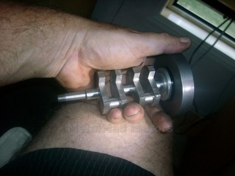
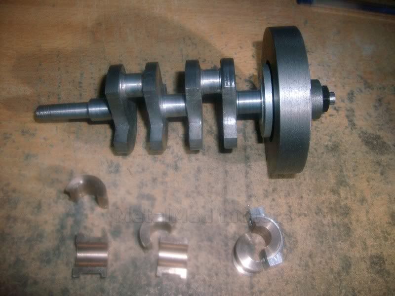
Fourth, the crankshaft is poised on knife edges or rollers, to act as a balance, and the assessed weight is hung on the crankpin; the counterweight is then adjusted until it "stays put" in any position of rotation. This may entail either adding or subtracting metal at the counterweight, such as by fitting lead "slugs" in suitable recesses where they cannot be thrown out centrifugally, or by filing or machining away the surplus. In some cases, lightness of the balance weight may be remedied by reducing the web on the crankpin side, or enlarging the centre hole in the later, always having due regard for retaining a margin of mechanical safety.

[Ron: Notice the "knife-edges" in the photo? Looks to me like two pieces of drill rod held in position on the leveled surface-plate by four small lumps of modelling clay. That is an idea well worth remembering!]

The weight necessary to carry out this operation may be made up from sand, lead shot, or any suitable material to hand; as may be seen, metal washers were used in the case illustrated. In the absence of a scale pan, a small bag may be used. It is important that the means of suspension on the crankpin should be arranged to produce the minimum friction. In the example shown, a small plug was made to fit inside the hollow crankpin (its weight being duly allowed for), having an extended pin of small diameter, on which the hook of the scale pan was hung.

The figures in the example illustrated are as follows:


Piston, with rings and gudgeon-pin .. 83 grms.
Small-end of connecting-rod .. 21 "
Big-end of connecting-rod .. 25 "

(83 + 21)
----------- + 25 = 77 grms
2

(the amount to be cancelled out by counterweight)

Should the designer adopt a different figure for the proportion of reciprocating weight to be balanced, this part of the calculation must be suitably modified. This formula, however, has been used with success, not only in models, but also for larger engines which have had to work under exacting conditions.

I have described this procedure in detail, as it is of interest to a large number of readers, to judge by the number of individual queries I have had to deal with, and I trust that this will clear away the last remnants of mystery regarding this subject.

I have stated that these conditions apply to any orthodox single-cylinder engine; it is also correct for machines having a similar order of motion, such as high-speed pumps or air compressors. Balancing problems should not be confused with effects caused by working pressures, though these produce their own reactions, and may affect smoothness of working. In many small machines which are not required to run at very high speeds, little attention is given to the finer points of balancing, and within certain limits, the results are fairly satisfactory.

 
Hi Tel
Thanks Mate
With the content pilfering that has been going on at the moment, i thought its better to be safe then sorry :big:

Hi John
Thanks for that
that balancing data is just what im looking for!!
were there pics in that book?
and what is a "spring balance" exactly?
Pete
 
A single cylinder engine cannot be balanced perfectly (at least not without additional balancer shafts). The best that can be done is a compromise. Classic single cylinder motorcycle engines used a balance factor between about 45% - 66% of the reciprocating weight. The choice depends on the the direction in which the resultant vibration should occur. This is often dependent on the engine mounting. A 90 degree V twin on the other hand can be balanced well by counter weighting the crank with the weight of one piston and con rod little end.

I would be really interested if anyone has any suggestions for some balancing software that can do all the vector maths for a more complex engine. This can be done by hand, or even graphically, but is fairly complicated (to me anyway).

 
Hi Bill
a little bit of vibration will not worry me too much mate
if she runs ok then any thing else is a bonus :big:
Pete
 
a spring balance is just an old type weight scale all i use is a digital kitchen type cooking scales i bought them for weighing all the parts ie rods etc in the multipile cylinder engines to get them all individually the same weight
i can send you the whole text regarding balancing via email it was a bit long too post the full text might make it a bit clearer
 
Hi Mate
please do, it looks like a great read but it looks like it will be some time before i get the crank finished.
This weekend is a bust as i have to go to a wedding this arvo and the missus birthday tomorrow.
have you been doing much?
Pete
 
hi there
good that info can be a help not something to read when tired
just setup my new lathe so am going to make a start on a little de dion single casting set
plan is in german so could be interesting
 
I have enougth problems reading english plan sets :big:
Have a bit of a problem at the moment, My mill is stuck between gears and so far just will not move.
Im thinking about making a longer metal handle to replace the plastic one but sure wish i still had the old RF 31 as a back up.
The Hafco HM 48 may have only been 6 months old when i got it but they must have been a hard few months :big:
Pete
 
I was able to get my mill unstuck without damage by using a stud remover.
When i get a chance ill make a longer and stronger handle for the gear change :)
With the mill sorted i got stuck into the main bearings.
The hole is still a bit under size so I'm not ready to install the Crank just yet.
Pete
SANY0078.jpg

SANY0079.jpg

SANY0080.jpg

SANY0081.jpg
 
Pete,

Not saying much but following along................I reckon it's going to be a nice engine. :bow:

Best Regards
Bob
 
Following right along with you Pete, looks great and I am enjoying your build. Dave
 
Pete,

Looking great mate!....you know I'm watching. ;D

Dave
 

Latest posts

Back
Top