V-4 oscillating engine

Home Model Engine Machinist Forum

Help Support Home Model Engine Machinist Forum:

This site may earn a commission from merchant affiliate links, including eBay, Amazon, and others.

jthulin

Well-Known Member
Joined
Apr 21, 2009
Messages
77
Reaction score
1
Hello everyone thanks for looking at my project. This is the first time that I have posted an in-process build. As I am a new member here, the engine was started quite a while ago and is fairly well along. I plan to make a few posts to bring things up to date.

I am building a “tweaked” version of Jan Gunnarsson’s V-4 oscillating steam engine. I saw the plans in a book borrowed from the local library quite a few years ago. At the time I was interested in sterling engines, but this V-4 caught my attention. I have since gone back and scanned the plans as a starting point. I wasn’t interested in building to the metric plans, so I redrew the engine, adapting the details to nominal inch sizes. An important objective was to retain the “curb” appeal that originally caught my attention.

So, without further rambling, here we go…
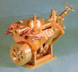
This is Jan’s completed engine:

v-4photo.jpg


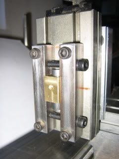
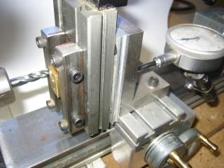
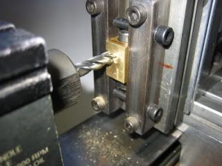
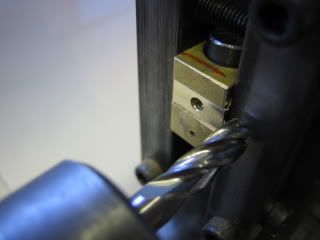
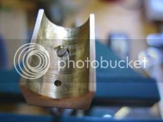
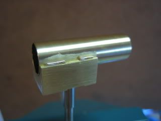
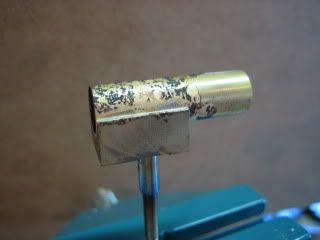
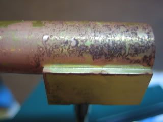
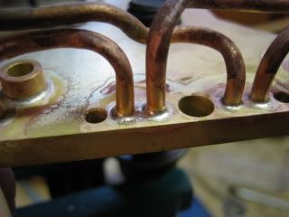
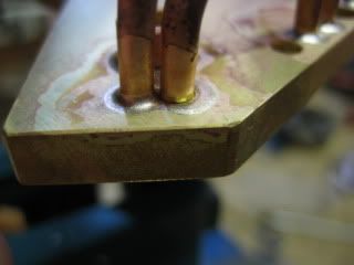
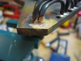
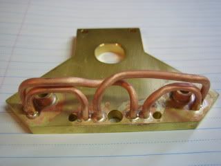
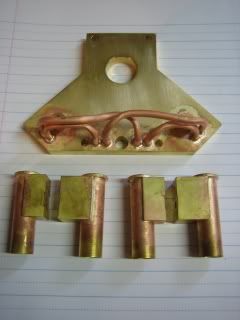
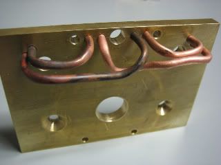
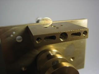
This is one end plate with steam pipes. The pipes are to be silver soldered in place at a later date. At this time the end plates are still oversize- they will eventually be cut down into the “Y” shape.

IMG_6458.jpg


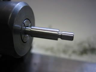
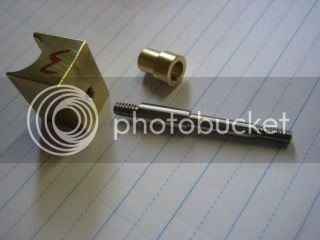
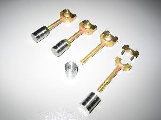
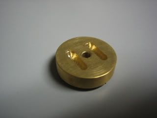
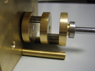
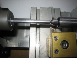
Here are the connecting rods and stainless steel pistons. The con rod bore is 0.25” and the bolts are 2-56. Piston diameter is 0.375”.

IMG_6449.jpg


More to come...
 
Darn good start there! :bow:

I'll be watching with keen interest as this motor is on my must build list.

Are you going to use silver solder or do you mean that you will be silver brazing?

The higher temperature of silver brazing is a little bit more of a clean up process. It seems to me that copper lines soldered (even with soft 60/40) to brass wouldn't need anything stronger.

With my limited experience I need to get a little nosy and ask questions.

Thanks.

-MB
 
Metal Butcher said:
Are you going to use silver solder or do you mean that you will be silver brazing?

Thanks MB,

I guess I need to be more careful with terminology :-[. I plan to silver braze with Silvaloy 45. Why? Because I have some and find it pretty easy to get nice results. I just recently started using citric acid as a cleanup bath and am happy with the results so far.

I think I will braze the pipes and the cylinder pivot bosses in the same go to avoid un-doing the previous job...
 
Great Jeff, look forward to seeing more progress. I bet this will be a little 'power-house' of an engine.

Do you know about 'Wood's Metal'? It can be a great help for small bore pipework with multiple bends.

Keep the pictures coming!
 
jthulin said:
Thanks MB,

I guess I need to be more careful with terminology :-[. I plan to silver braze with Silvaloy 45. Why? Because I have some and find it pretty easy to get nice results. I just recently started using citric acid as a cleanup bath and am happy with the results so far.

I think I will braze the pipes and the cylinder pivot bosses in the same go to avoid un-doing the previous job...

Many people refer to what I call "silver brazing" by using temps over 1100 degrees and Silvaloy 45 you mention or Safety-Silv45 as "silver soldering".

Some refer to it as "hard soldering."

I Call "soldering," "soft soldering," and "hard soldering" a process that does not require a temperature over 600 degrees to melt the "soldering" alloy, and it does not have any added yellow colored metal.

I was holding some "silver solder" the label said "silver solder" prior to purchasing it at a show, a stranger came up to me and said "that's not silver solder, silver solder is a gold color."

Gold? Gold is a gold color. I should have asked him if he wanted to buy a pound of uncut black diamonds real cheap! LOL

Your terminology was fine. I just wanted to be sure of the process you were using based on my past and present confusion.

Edit: My definition of "uncut black diamonds" is hard coal.

-MB
 
The first part made was actually the steam manifold. Shown here, these ports are what the steam pipes connect to:

IMG_6455.jpg


The reversing valve sits on the top of the manifold and has 2 slots that line up with pairs of the 4 holes seen on top of the manifold. This is the bottom of the valve:

IMG_6457.jpg


Here is a photo of the latest part made, the crankshaft:

IMG_6456.jpg


Stay tuned, more to come...
 
I'm liking what I'm seeing so far Jeff ;D ;D Nice work.

BC1
 
Metal Butcher said:
I was holding some "silver solder" the label said "silver solder" prior to purchasing it at a show, a stranger came up to me and said "that's not silver solder, silver solder is a gold color."
FWIW, I just got in some Easy-Flo silver solder with cadmium that has a light gold tint to it. The non-cadmium bearing "Easy" I got from a local jeweler supply is bright silver in color.
 
jthulin, That crank looks really good! If you brazed it I can't see a trace! Super!

shred, I'm curios, does it say the melt temp on the silver colored jewelers solder?

-MB
 
Thanks to all for the kind comments ;D.

As per the Silvaloy 45, the melt temp is something like 1125 F with a flow at 1145 F just from memory. It has a goldish tint and does contain cadmium. An equivalent to this alloy is also available cad free and claims to be a color match to stainless steel.

Sorry MB, no brazing on the crank scratch.gif. It is held together with Loctite 620 retaining compound for now. Jan G called for this method in the plans, with pins for added security if felt needed. Undecided for now if pinning the crank is necessary ???.

 
Metal Butcher said:
jthulin, That crank looks really good! If you brazed it I can't see a trace! Super!

shred, I'm curios, does it say the melt temp on the silver colored jewelers solder?

-MB
It doesn't have a temp listed on the packaging since it was wound off a big reel, but jeweler's solder is pretty regular because they do so much multiple-assembly work where they rely on the different temperatures to keep previous assemblies from falling off when adding new ones. IIRC the one I have (Cad-free 'Easy'-- approximately 45% silver) melts at about 1250 with flow around 1325'F. If you see my notes in the Slightly Loco thread, you need a nice 'cooked carrot' (thanks to whoever came up with that one) orange to get it to flow.

Here's a pretty good chart (and US source) for some of the common solders-- http://www.sra-solder.com/brazing_wire.htm
 
Finally a little more progress.
Got the cylinder pivot shafts turned and threaded from 18-8 stainless. Large diameter on shaft is 0.187" and the thread size is 6-32:

start with center drill
IMG_6614.jpg


ready to turn step in shaft
IMG_6615.jpg


threading one end
IMG_6618.jpg


one end finished
IMG_6619.jpg


short end ready to thread. Found out very shortly after this photo was taken that the reduced shaft was not strong enough to withstand the torque of threading and sheared off after about one turn of the die :mad:
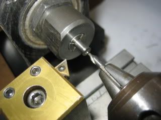
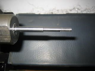
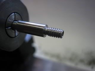
. Solution was to cut the thread and then turn the undercut after Thm:
IMG_6625.jpg


finished short end
IMG_6626.jpg


one of 4 finished shafts with a cylinder pivot and bushing
IMG_6627-1.jpg


No appologies for slow progress- will post as I go...
 
I've run into that question before.

Above 800F it's called brazing, unless the spelter is silver bearing in which case it is often called soldering. Most welders will argue that it is always Silver Soldering.

Below 800F it's always called soldering.

Check the Machinery Handbook......but I've had that argument before...the definition is in there.


Dave
 
Managed to finish 4 each of the pivot bushings as in the previous photo. Next was to mill the slot across the back of the cylinder base. Here are some photos that show the milling operation in the Taig lathe:

General view of a Taig compound slide mounted on a home made angle plate to create the vertical slide for milling.
IMG_6712.jpg


One cylinder base held in special vise ready for milling
IMG_6713.jpg


1/4" end mill ready to cut. Also notice the dial indicator mounted to indicate depth of cut.
IMG_6714.jpg


Part way through (0.015" depth). The end mill was actually spinning when this picture was taken!
IMG_6716.jpg


Completed cut.
IMG_6719.jpg


This was a pretty easy milling job for this setup. It has little difficulty with a 0.06" deep cut, 3/8" end mill in brass. Not bad for a little machine.
 
Also had time to silver braze the cylinders to the bases. The cylinders were simply cut from a length of K&S brass tubing with a 3/8" ID. The plan was to braze the pivot shafts into the bases in the same operation:

Here is a cylinder base screwed onto a shaft with a small piece of braze alloy in the "pocket" above the shaft.
IMG_6721.jpg


Flux was applied to the base and the cylinder rolled slightly in the flux for good coverage. Alloy was placed along the edge of the joint.
IMG_6723.jpg


Here it is after application of heat.
IMG_6725.jpg


All of the alloy disappeared into the joint, leaving a tiny fillet visible here.
IMG_6729.jpg


I expected the shaft to be braxed as well, but zero out of four stuck! I know the pieces got hot enough, and have used the same alloy and flux to braze stainless to stainless (shafts are SS), so I have yet to figure out why this didn't work ??? At this point I may just loctite them in place.

Next up is to drill the steam passages through the bases into the cylinders, then align the pistons to the inlets. If you care to look back at the piston arrangement, you will see that they are threaded to the connecting rods. The task now is to adjust them to the correct position relative to the inlet ports and lock in place with the nuts. After that, braze the cylinder caps onto the cylinders.
 
I expected the shaft to be braxed as well, but zero out of four stuck! I know the pieces got hot enough, and have used the same alloy and flux to braze stainless to stainless (shafts are SS), so I have yet to figure out why this didn't work Huh? At this point I may just loctite them in place.

Maybe because you were applying heat from the top and the solder flowed towards the heat? Or maybe there was some cutting oil still in the thread? Just a thought....
 
Thanks for your thoughts Paul. You make a good point about the alloy following the heat. I am certain that any cutting oil was long gone, but I realized later that I forgot to put any flux on the thread :wall: so, same effect...

I have now silver brazed the top caps on the cylinders and also the pivot bushings and steam pipes into one end plate. Should have time for the other end plate tonight. Note to self: flux, flux, flux ;). Pictures to follow.
 
Picture time ;D

Here are 4 successful joints:
IMG_6787.jpg


And one not so successful. A close look at the right side pipe will show no fillet. Probably another inadequate flux application. 1 bad joint out of 20 isn't too bad though, right ???
IMG_6786.jpg


Here is the same joint, re-brazed. It is sitting in the acid bath as I type...
IMG_6789.jpg


Here, then is one end plate after a swim in the citric acid:
IMG_6795.jpg


And one last picture with the cylinders and their new caps:
IMG_6792.jpg


That's all for now...

 
Good Job Jeff

Thanks for showing your build.

Stew
 

Latest posts

Back
Top