Treadle Finger Engine

Home Model Engine Machinist Forum

Help Support Home Model Engine Machinist Forum:

This site may earn a commission from merchant affiliate links, including eBay, Amazon, and others.

Lamachina58

Well-Known Member
Joined
Nov 13, 2010
Messages
74
Reaction score
0
Treadle Finger Engine
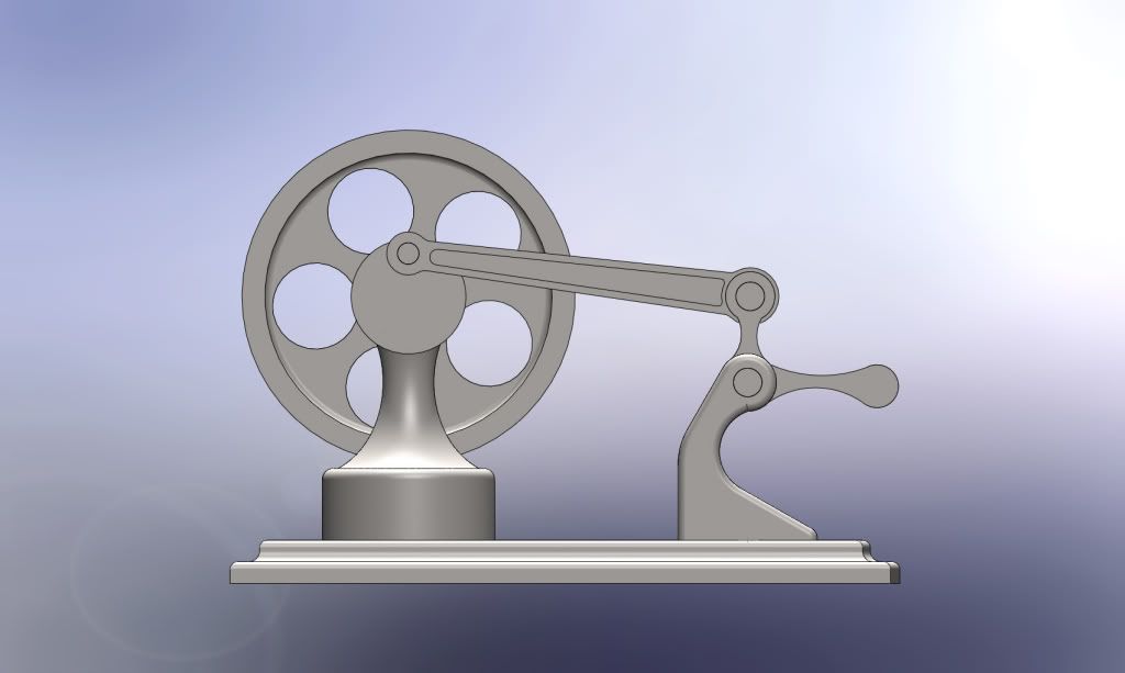
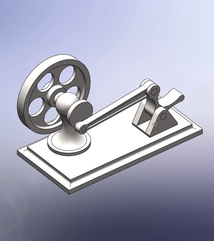
I've drawn this model up in solidworks as a CNC project for the students in our CNC course at the University of Montana Helena College of Technology.
Our goal is to manually program most of the parts using G-code.
I've based the design off many I found on HMEM and links from other users build threads. Any suggestions would be appreciated!
One tool we use that is extremely helpful is a small program called NCPlot. It is a simple program that helps you visualize the toolpaths as you write the code. This allows us to proof our programs and free up our machines.
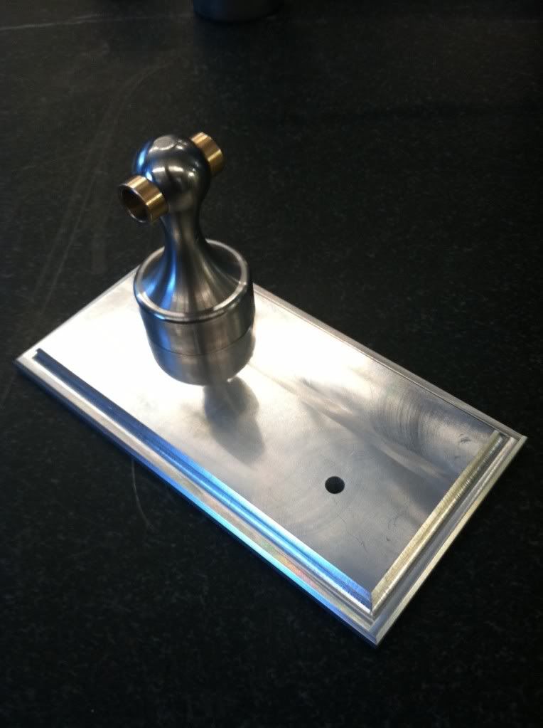
I will post photos as we go!
FingerEngineAssembly.jpg

Treadle Finger Engine
Enjoy!
Tom
 
Thanks for sharing this cool little engine, I will have to build one soon :D

Regards,

Will R.
 
Tom,
It will be a nice project as it does not require anything extra tom make it run. Sure beats making the small brass hammer as a project.

One suggestion. If there is not enough room between the treadle and the base with the treadle in its down position for a generous clearance for a fat finger, then relieve the base so there is not a pinch point. A lot of energy is stored in even a small rotating flywheel. It can easily put enough pressure to cause the loss of a finger nail. and can happen to kids if all ages.

Gail in NM
 
Tom,

You might already know, but other people might not, for very smooth operation, there is a critical bit when it comes to making these engines, and that is the relationship between position of the pivot points (on the height) and the length of the conrod.

I have put a small C-o-C at the end to show you what I mean.

I have forgotten how many of these I have made over the years

John.

finger twiddler.jpg
 
Well Gail, that is a really good point, back to the drawing board and John, double back to the drawing board! I really appreciate the input! I don't want a student project that doesn't work.


And yes this is way more fun than the classic punch and brass hammer projects!
 
If you want a real fancy one, put another treadle, crank and conrod on the other side of the flywheel, operating at 180 degs to each other, so you use two fingers.

They reckon they are very difficult to keep running.


John
 
Bogstandard said:
If you want a real fancy one, put another treadle, crank and conrod on the other side of the flywheel, operating at 180 degs to each other, so you use two fingers.

I was thinking about 90 degs.,so it will never get "stuck" at TDC or BDC ;D
 
Dave,

Putting two at 90 degs apart would be masochism. At 180, you stand a chance, as when one is coming up, the other is going down the same amount, if turned into sound, flip--equal beat--flop, at 90, it wouldn't be an instinctive movement, quick flip-flop-pause-quick flip flop. Flip equals right hand treadle, flop equals left hand (or other way around, depends on direction of flywheel). :big: :big:

You need to imagine what the treadles would be doing.


John
 
I took the suggestions in to consideration and came up with some changes.
If we get through this we can consider the double treadle. Take a look.
20FingerEngineAssemblyside.jpg


and..
12_01_24FingerEngineAssembly.jpg
 
I like it Tom....very nice lines. Am pondering doing something similar for our machine shop lab here rather than the usual projects noted. Best of luck with this...maybe you can post some student made engines in time.

Regards,
Bill
 
Just from looking at it Tom, it looks correct, mind you I couldn't tell if the first one you designed was incorrect, wrong view angle.

I am not saying that you have to have these ratios, but they are the ones I came up with and followed, and I never had trouble running them, except for one which had a lightweight flywheel, because children were to use it, but even that was OK when it got going.

Here's a couple that I made and gave away (as I normally do), made to that formula I showed.

[ame]http://www.youtube.com/watch?v=ezOawsPXMns[/ame]


John
 
John,
This video is perfect to share! Thanks. The dimensions I had were off from your suggestions and I've adjusted it accordingly.
I have a question though.
Last week I designed a trials motorcycle footpeg for a company in England and the customer said in one e mail "make it bogstandard!" . I google it but he didn't clarify what that really means.
Confused in Montana.
 
John,

Perhaps you need to explain what "bog" means in colloquial, British English.
 
Maybe he hopes the footpeg will become the industry standard. It is not plain, S.S., investment cast etc.
What is Bog?
 
Rooting thru my archives, I actually found a video of a finger engine I made for a little competition we held on here.

Only hand tools were allowed, and the build must include some part of a wire coathanger.

This really does prove that finger engines can be made out of almost anything and will run if you get the pivots in the correct positions, and run well.

[ame]http://www.youtube.com/watch?v=kxk4_pTyRug[/ame]

This one is still sitting in the back of my shop and even though the green wood has now fully dried out and the lashings have gone a little slack, it still runs well.

Maybe I should plant it and see if I get a finger engine tree.


John
 
We are well on our way (my cnc class) to making 15 treadle engines. Students are programming all of these parts with G Code, no cheatin with Gibbscam or MasterCAM yet!
Here is a base and column finished today.

Baseinmill.jpg


I assigned 70 pages of reading and was informed it is SuperBowl weekend. I didn't know that but too bad, machining comes first!
 

Latest posts

Back
Top