Tiny Stirling

Home Model Engine Machinist Forum

Help Support Home Model Engine Machinist Forum:

This site may earn a commission from merchant affiliate links, including eBay, Amazon, and others.
Great Project Nick!

Your making good progress too! I really like the scale of this engine, and yours is turning out to be quite nice. There is nothing better than a handmade gift, especially one as awesome as this.

Would Egg Carton foam be sturdy enough, or even the foam you get with packaged beef?

Kel

 
kcmillin said:
Would Egg Carton foam be sturdy enough, or even the foam you get with packaged beef?

Kel

I reckon thats a good idea kel, quite a lot of food packaging is closed cell foam.

Vic.
 
Thanks for the advice guys and sources of displacer material. I was going to try putting lightening holes in my nylon one but I can see this foam material is still going to be a lot lighter so might just use some food stuff packaging.

Nick
 
Got a quick update tonight. I only managed 2 hours work, not pleased with the results but nevertheless it yielded 2 iffy components :bang:

I set about making the 2 bearing uprights, one is was to be soldered (I think actually I'll glue it some how instead as I don't want to mucky up and have to clean everything) and the other bolted to aid assembly.

I started by finding some suitable brass, as luck would have it I found some 1/16" plate which is what I had designed it for - some 3/8" wide strip would have been ideal but this would be ok.

I made a bit square and marked it out, first mistake was annealing it - this made it black and difficult to mark out.

2010-12-1322-38-02_0001.jpg


Cut the two ends off and filed to size, then put in milling machine to drill bearing hole. Mistake 2 - managed to drill off centre and using a blunt drill made a massive burr on the other side.

2010-12-1323-02-32_0002.jpg


At least the hole was sort of square, but this is so thin I can just give the holes a bit more clearance to reduce friction if anything is binding anyway.

2010-12-1323-14-18_0003.jpg


I could use this rod to help me hold them together while I filed one side to make the hole central again - got bored of this to be honest and it's already 20 thou undersize on width now - doesn't really matter but it's frustrating.

My marking of the radius on the top had now gone so I had to do it by eye - filing button would probably have been the order of the day here but for 1 rad on this thin bit of metal it was hardly worth it.

Here are the finished bits, even managed to drill the other hole off centre for the bolt too. A pretty poor night really, lots of scratches in it too. :(

2010-12-1400-07-48_0004.jpg


Final mistake was that I forgot I'd used 4mm instead of 4ba for the bolt, therefore my clearance hole isn't big enough, which means I couldn't do a trial assembly. By the looks of it I still have a burr on the top plate anyway so that'll need to go first.

I should really have paid more attention to these, because the flywheel sits between them, they are quite visible. I don't have time to go back and start re-making parts now though, I think I'd rather just prove the design if I can.

Well, that leaves me with 4 parts to make ... 2 small ends, crank and piston. So 2-3 more nights at least, hopefully I'll be finished on Friday. I will probably need to re-make or modify the displacer though which will be too heavy.

When I was eating my bacon sandwich from the canteen on Friday it occurred to me that the box may be the sort of material people were talking about:

2010-12-1400-11-52_0005.jpg


Or alternatively, the lid I stole from the fridge could be used to seal up my nylon displacer after I have attacked it with a drill!

Nick
 
sorry I haven't been on for a while but this will be my final update on this version of the tiny stirling engine.

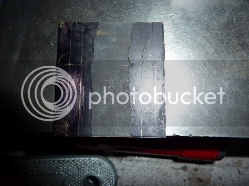
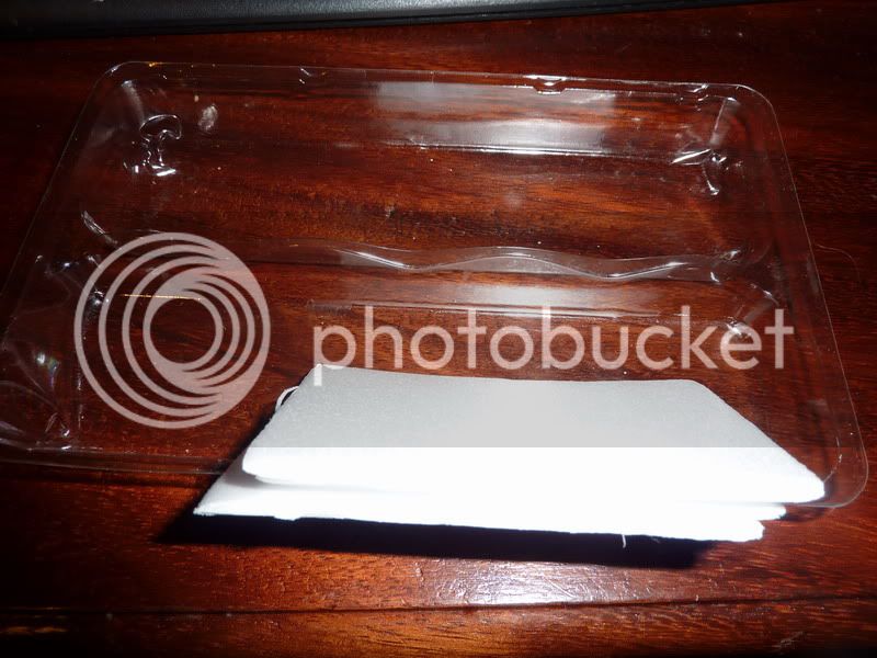
Here is a pic of the lightened displacer, as I said, it didn't make it that much lighter to be honest, maybe 30%. Apologies for these pics, I was just having one of those days and not a lot would go right!

2010-12-2319-38-32_0001-1.jpg


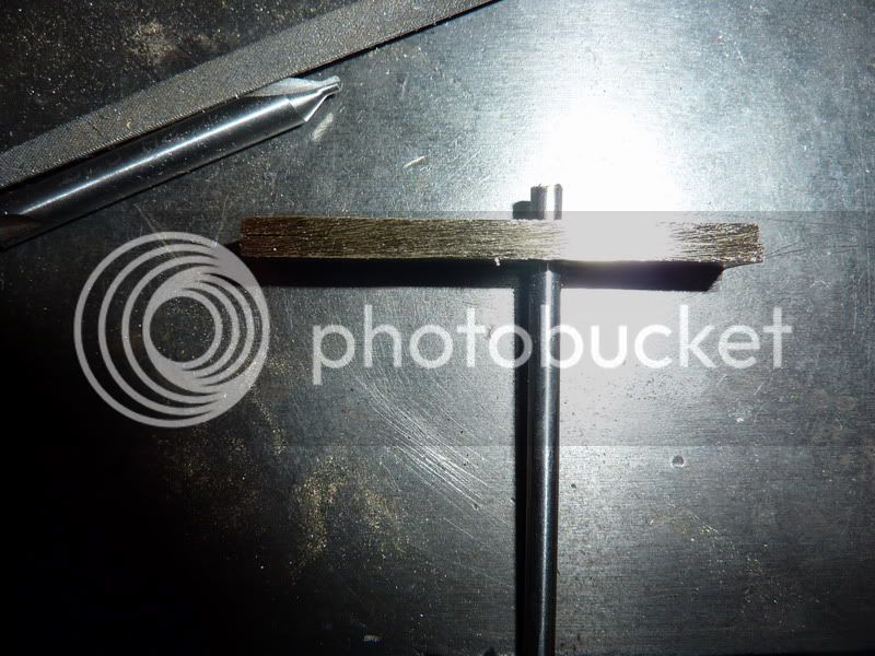
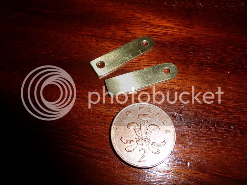
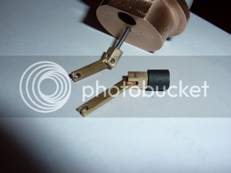
Next was the piston as I said below, then the two small ends. I didn't have any 1/8" dia brass (thought I had some brazing rod but couldn't find it) so I made some square versions from some flat 1/8" brass strip. I also decided to make them a tad wider than 1/8" in the other plane so I would have more room for the slot. I selected the right drill to give a nice push fit for the pins so everything together with a pretty easy press fit. Here are pics of them assembled to rods. I was running a bit short of time by this point so sorry, I didn't get any machining pics but there wasn't much to show.

2010-12-2319-53-34_0001.jpg


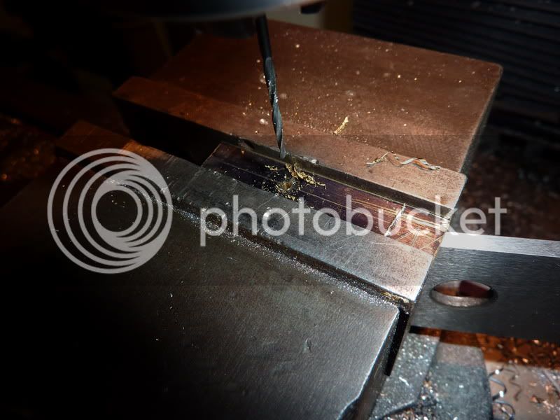
The last piece was the crankshaft. I started making this from 3/8" square brass and quickly screwed the diameter up resulting in a wobble on the flywheel before I'd even started on the journals. So that bit got scrapped, then I could only find 3/8" square steel. This was bought about 13 years ago for my 5" gauge Sweet Pea locomotive project that hardly got started. It actually cut nicer than the brass which I was pleased about.

This was a tricky component to make. I had to decide on the right order of machining operations so as to leave enough structural integrity so that it wouldn't bend.

The first job was to centre it in the 4 jaw. That wasn't too difficult as I found out 3/8" was the smallest size my 4 jaw would go down to - this became a problem later. I faced each end to overall length then turned the longer plain diameter for the flywheel and the 1/8" spigot for the bearing. Turned it around and did the same on the other end so each end was concentric (within the accuracy of my 3 jaw - good enough).

That's when I was going to put it back in the 4 jaw to offset turn the journals but of course I couldn't, the 4 jaw was too big, when I tried to get the offset the jaws just clash into each other.

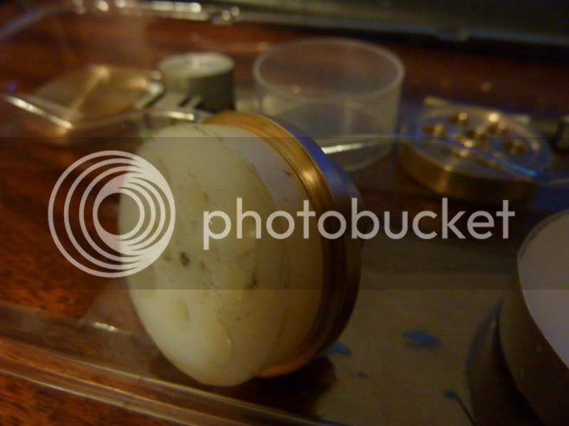
So I decided on a fool proof way of getting the 1/8" offset to give me 1/4" stroke. I just put a bit of nylon in the 3 jaw, offset by 1/8" with a bit of packing under 1 jaw, centre drilled and drilled a hole for a tight fit on the plain diameter, then put a saw cut through to the hole along the length of the offset bush. I then clamped the crankshaft in the bush in the 3jaw. I was struggling to get it to grip the shaft but when I did, I took too big a cut and it mangled the nylon and pulled the shaft out - luckily or miraculously no damage. So I decided to make an alloy split bush instead by the same method. This gripped much better.

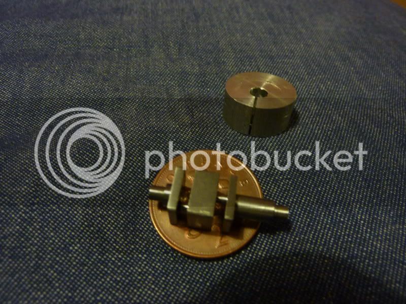
I turned the journal furthest away from the chuck first, then the one nearer in, as I said so it still had enough strength. This worked pretty well except I possibly got a little frightened as it was approaching 1/16" diameter and stopped a little large.

When I took the crankshaft out, it had turned out well except I don't think it had achieved the 1/8" offset I required. How could this happen? I just assumed if I put 1/8" packing under 1 jaw that would do the trick, or did I need to work some geometry out? I've never even thought about it to be honest!

2010-12-2319-37-07_0002.jpg


This was on Christmas eve or the night before I think so I didn't have time to make a new one, I just thought I'd have to try it. The effect this would have is to leave dead space at the top and bottom of the displacer though - not good.

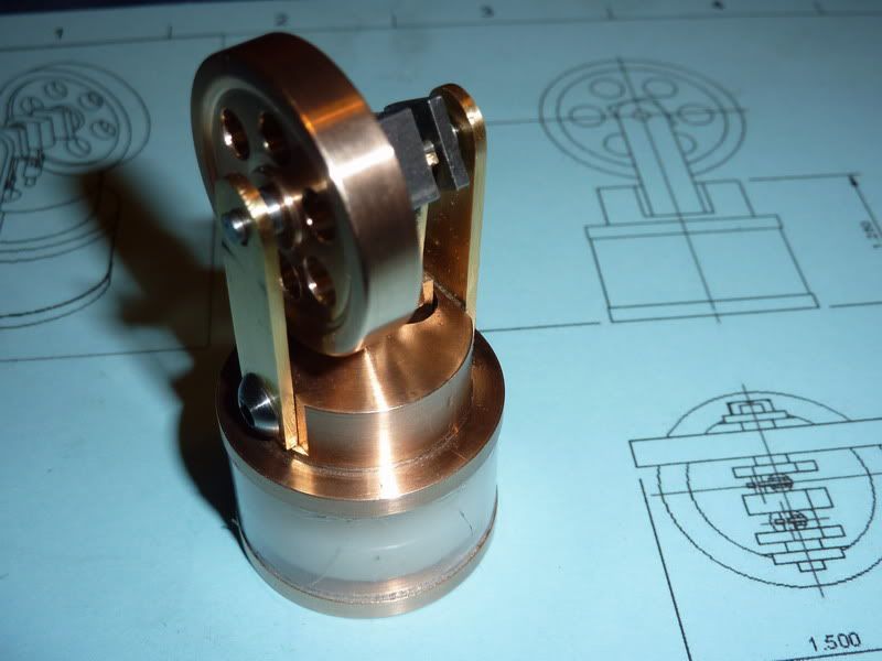
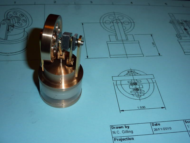
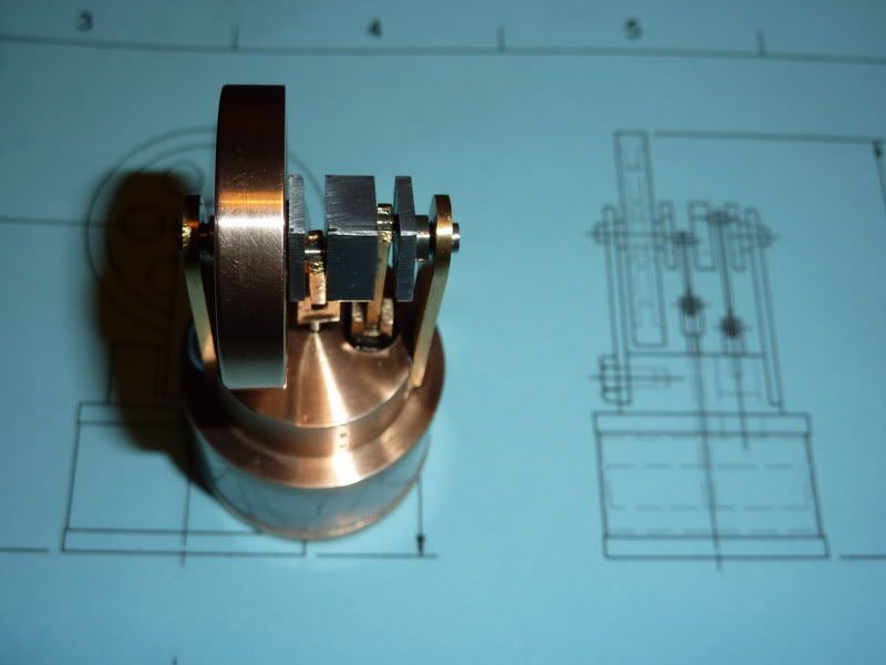
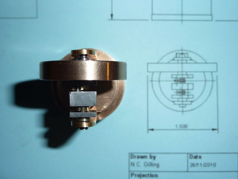
I thinkit was on christmas eve that I assembled the engine. Here are the assembly pics.

2010-12-2418-46-16_0002.jpg


2010-12-2418-45-42_0001.jpg


2010-12-2418-46-35_0003.jpg


2010-12-2418-47-50_0004.jpg


I forgot to mention, the other issue on the crankshaft was, I got carried away and forgot to make the journals the correct width. I thought ah, it'll be near enough jsut being the width of the parting tool - that way I only had to do 1 plunge for each. But it wasn't quite - When I assembled, one of the bearing uprights was to be super glued onto the top plate but to get it free running, I had to put a couple of shims under it to prevent metal to metal contact with the crankshaft and one of the rods - luckily I had allowed enough clearance on the length of the crank main bearings to allow this.

The other bit I found difficult was putting the rods onto the journals - these were the ones that had slits in the big ends to bend out, over journal and back in. With hindsight, I think I needed bigger slits. The plan was to bend them back with the long nosed pliers but I couldn't get in with those. I might have been able to do it resting on something and acouple of taps with a hammer and thin piece of steel. Not a great way of attaching the big ends really I don't think. May have been better building a crankshaft up of 3 or 4 bits but I thought I'd try to be clever and make from one piece!

The engine seemed very free running, I tried it on top of a flat bit on the heated towel rail and couldn't really get a peep out of it. It span over faster (10 or 15 revolutions) in the direction of running and only 4 or 5 in the opposite direction but nowhere near running I don't think.

Tried holding it over a tea light too and that was no different.

I think there are a few reasons it didn't run. The first, was the crank didn't have a long enough stroke leaving too much dead space in the system. Secondly, the fit on the displacer rod and piston could have been better. Thirdly, friction was possibly still too high even though I thought it was free running enough. The fourth could be the weight of the displacer, although the assembly seemed fairly balanced to me, it didn't seem to settle in any particular place. It had the weight of the piston and pin etc on the other side. Maybe the flywheel was also too heavy. If I make another, I will address all of these issues and hopefully have a runner.

I could provide drawings but I don't think anybody would want to risk spending the time and effort making something that might not work so I'll wait until I've built a working version.

My dad seemed happy with his present. Put a copy of the general assembly drawing wrapped up with it so he knew I'd design and built it with the intention of giving it to him for Christmas. I was gutted to have to give him a non working model though, if I do make a working version his will be swapped for it!

Nick
 
Nick, Happy Holidays.

I salute you and anyone who 1. makes an engine for a gift, 2. works in such a tiny scale, 3. posts their work on an engine still in development, 4. Does all of the above at the same time.

I have not seen the engine you mention as inspiration

that said, I have no experience with sterling engines and very little engine building experience in general but it appears to me that you have alot of mass in your rotating assembly. the flywheel combined with the grank throws and the wieght of the rod ends and clevises all add to the load the engine is trying to turn. And most of the weight appears to be close to the center of rotation which does not help your flywheel affect. it may help the engine considerably to lighten all of these parts (with the exception of the rim of the flywheel) to the extent possible with your equipment.

Randel
 
Thanks Randel, I did think that as I was making the parts, but it didn't feel anywhere near as bad as it looked. The parts are all tiny, however, you may be right relative to the size of the engine it may be too much and the relatively heavy flywheel may eclipse any feel of the other overweight parts. I won't be trying to get that engine to run but will try to account for all of this in revision 2 of the engine! Thanks,
Nick
 
Randel makes a good point. The engine looks very massive for an LTD Stirling.

Try sticking the engine in the refrigerator for an hour or two, then attempt running it over a tea candle or similar. The massive upper cap on the displacer will stay cold for a while and give you a good temperature differential for long enough to decide if it will run at all on a modest differential.

Have you tried it sitting on a plate of ice in a warm room?

When I build mine (it's in the queue), I intend to assemble the connecting rods to the crank as the crank is assembled. That slit business of Jan's, even in very thin material, looks problematic at best.
 
I recently built a small stirling just for a weekend project that could be started and finished in a short time frame. It's not quite as small as yours appears to be, but small none the less. I learned a few things that might help you out with yours.
1) The torque available is very low and, therefore, friction will kill you. Everything needs to be very free running. I used some bearings from a VCR head and the mainshaft with the flywheel would spin for a good twenty seconds after a hand spin with no pistons or anything attached. I used similar bearings for the rods. They are great bearings and VCRs are really cheap/free so they are easy to get. R/C cars and helis use even smaller ones and they are pretty cheap as well.
2) The seal between the displacer rod and the top cover has to be good, but not draggy (see #1 above). Mine uses a fairly long teflon bushing and I had to fuss with it a bit to get it "just adequate". Probably could be better, but it works. A bit of lube helped here.
3) The power piston fit must be good and not leaky. A bit of lube helps here as well.

Anyhow, after a bit of fussing I did get the thing to run off a spirits lamp and it now "powers" a small fan attached to the flywheel. I have an old BING toy Stirling from about 100 years ago and it runs great without and obvious fussyness to any of the parts although, as mentioned above, everything is pretty loose. It's only a toy after all. Bit more instructional than something with dead batteries and obsolete software and, as a added plus, you can burn the whoopee out of you finger which can be a good object lesson for eager young minds.
 
Thanks Marv and Ed, looks like the mass and friction could be half the battle. I agree I don't really like the split, bendy big end thing much. I intentionally made the top plate from 1 block so it would act as support for bearings, I could bore cylinde directly into it giving giving minimal dead space and it would provide good support/ seal for displacer rod. Also, as you say it's a large mass so at room temp with only plastic between top and bottom it would take a long time to heat up. I haven't tried putting it in the fridge but tried it over a tea light with no joy. That must have been an 80 - 100 degree differential so doubt it would have run. Hopefully with all the improvements people have suggested and have been obvious when I've made bits I'll get a running version. I think the overall design is sound.

Nick
 
I hope you get it running Nick and when you do I wouldn't mind a copy of the plans.
I must admit that on this occasion I didn't much like the look of Jans version of a tiny LTD Sterling, much preferring the look of the one in the movie you showed. I liked the turned support column and many of the other parts as well.

Vic.
 
Vic,

Thanks for the interest. I think I need to drop back onto poppin to finish that first then have another stab incorporating all these learning points then you are welcome to the drawings if it runs! I think Jan has modified his a little too now. I think his very much had speed in mind using ready made glass tube for cylinders and coins for the top and bottom plates and flywheel. I did prefer the youtube one too though.

Nick
 

Latest posts

Back
Top