Tiny Stirling

Home Model Engine Machinist Forum

Help Support Home Model Engine Machinist Forum:

This site may earn a commission from merchant affiliate links, including eBay, Amazon, and others.

NickG

Well-Known Member
Joined
Jun 20, 2008
Messages
1,025
Reaction score
19
Oh no, why have I started another project before i've finished the previous two? Well, it was Jan Ridder's fault again! He recently posted his Micro Stirling Engine on his website - I had to see it so asked for the plans, which he was very kind to send to me. The problem is, I just don't like making stuff from other peoples plans blindly! It never seems to suit my materials or processes so I have to change things - but I probably go too far.

This time I've tried to combine the best ideas from Jan's and another engine I found on youtube - see below:

http://heetgasmodelbouw.ridders.nu/Webpaginas/pagina_stirling_1_euro_10/frameset.htm

[ame]http://www.youtube.com/watch?v=dAV_nWTwWR4[/ame]

Mine is going to end up a little larger than these two mainly to make things a bit easier for myself and what I have to hand, it should also give it a slightly better chance of running.

I have done the CAD model which took a bit of working out and have now completed the 2D drawings. I did calculations to ensure the ratio of swept volumes between displacer piston and power piston are almost the same - this is quite important as it largely governs the temperature difference the engine can run on, of course there are a lot of other factors but I think this engine should work.

Please see attachment for the 3D model.

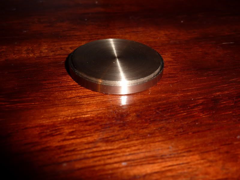
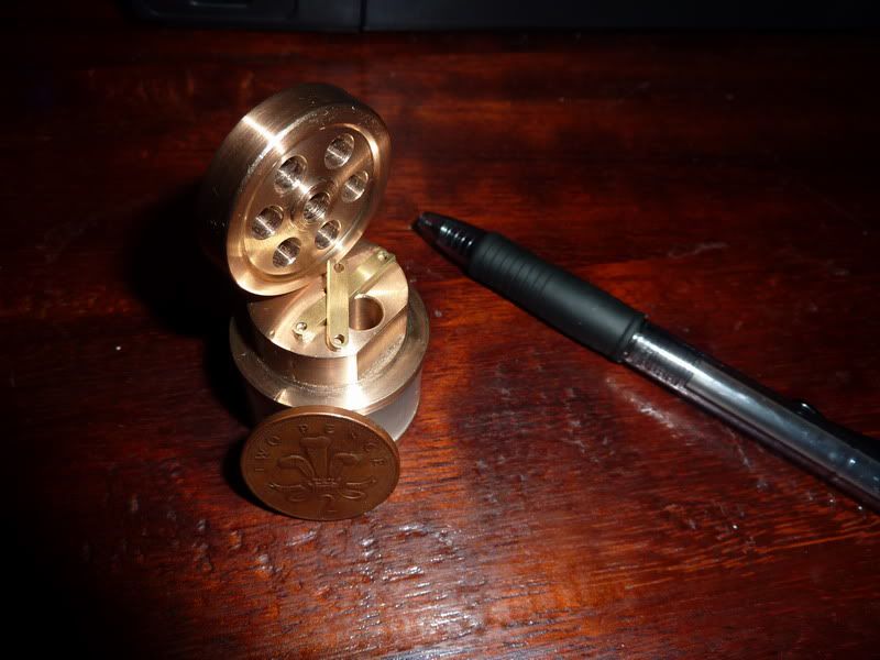
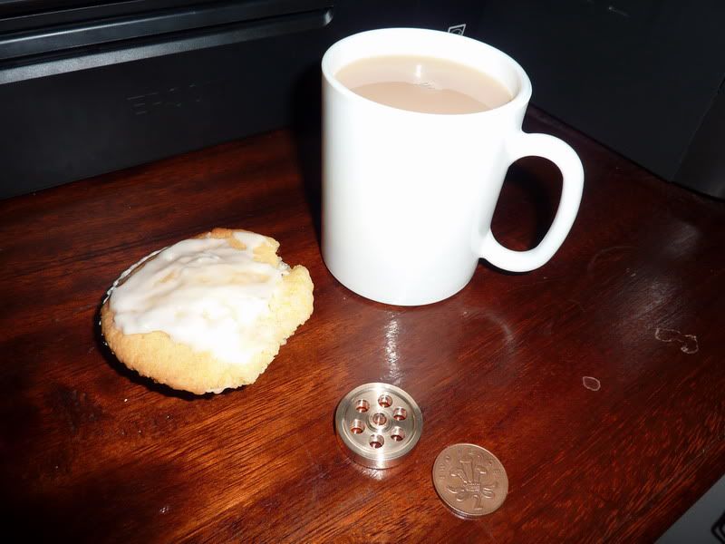
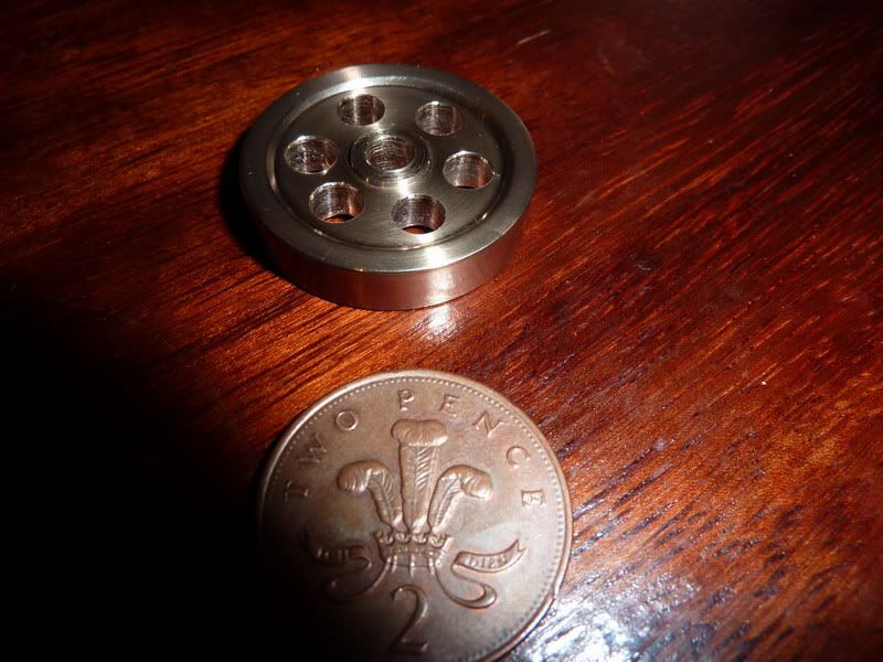
Tonight I started cutting first metal - A slightly frustrating night but it has yielded 1 component - I started off collecting some materials together but then got bored of that so started turning the bottom displacer cover or hot plate as I've called it on my drawings. I quickly realised that because of the thin register I need to turn that and part it off a longer piece of stock. I have some cast gunmetal that I'm using. The slither that I had planned to use has now ended up as the flywheel! This means I've already deviated from my drawings, when I felt the weight of the aluminium I'd planned to use for the flywheel I thought it was too light, so I thought I'd use the cast gunmetal and thicken it up by 1/16" to 1/4" thick. The diameter has ended up as 1.22" or something rather than the 1.5" I had originally planned. Actually, this now seems a bit heavier than I thought so may have to do the ally one after all but maybe keep the 1/4" thickness, then it might be heavy enough.

Anyway, here it is:
2010-12-0323-46-56_0001.jpg


The cake is 2nd hand, my 2 year old son licks the icing off but he didn't do a very good job on this one so waste not want not!
2010-12-0323-47-33_0002.jpg


Feel a bit disappointed that that's all I managed in a night but at least it's done. As I said, it deviates from the drawing in size and material. I couldn't be bothered to find / change tools etc either so the recess isn't quite right. I think I will modify the drawing just to widen the alloy flywheel. Unless this one works then I'll change it to brass. The plan is just to loctite it to the crankshaft - just easier for this little engine, it'll have no power so won't come loose.

This is probably the 2nd most complex part on the engine so at least it's a start.

Nick


View attachment Assembly.pdf
 
nice start, nick. I like the flywheel. where will you find a translucent cylinder like the one in the video? will you cut a test tube?

t
 
Tom,

Thanks, I'm not going to use a test tube though - well, for now. I found a plastic lid off some sun cream that I'm going to try so yes it is translucent. I guess it all depends how much heat I need to make it run, I might end up going to a test tube if I need a flame underneath it, or even a metal tube - I don't think it will detract too much from it not seeing the displacer move up and down.

Nick
 
very interesting build. Cannot wait to follow it!
 
Thanks Vedoula,

I just hope it works - it's going to be a gift for my dad for Christmas - I can't afford to buy anything as last Sunday both of our cars broke down! One needs a new engine and the other the garage can't find out what's wrong with it!

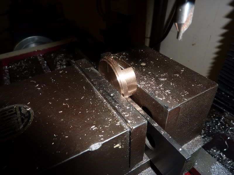
Done a bit more today - again, not as much as I'd have liked. More messing around sorting the parting tool out - it had remained in snapped form since I tried to part off some tough steel but I need it for this. I always struggle turning thin things like cylinder covers for some reason!

Not much progress to show, below is the hot plate or bottom displacer plate, the other side doesn't look as good as the parting tool was not on dead centre height so it left a bigger pip that it should of, then I had to file it down - no matter though as it's the underneath of the engine.

2010-12-0419-13-28_0001.jpg


I have almost finished the top plate which is probably the most complex part - touch wood it's gone ok so far, it had to stay in the milling machine though as just got to drill and tap the hole for the upright then it's finished. I got a good fit with the register on the plastic tube so am confident it will seal well. just need to work out what sort of glue to use. Maybe some quick ish drying araldite?


If it does work I will correct anything I spot in the drawings during my build and release them on here but I wouldn't want anybody else to start it incase it doesn't work! And of course somebody would end up making my engine before I'd made it!

Nick
 
Got a bit more done today - I bet people can't believe this ... I've been in the garage a few days running!

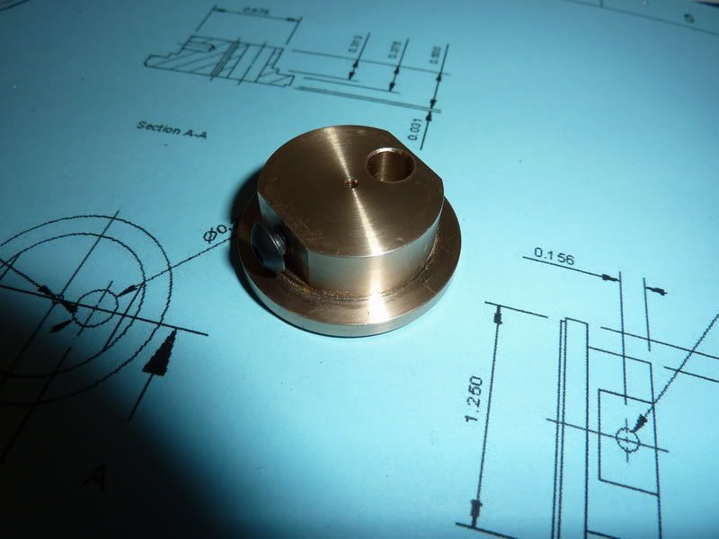
Started off by finishing the top plate which is combined power cylinder and displacer rod guide on my version. All I needed to do was drill and tap the hole in the right position 4ba - how hard could it be?

2010-12-0514-23-51_0001.jpg


Well, for me very hard apparently - I tried to be clever and tap it in the milling machine under power- normally I do it loose enough so the tap will spin in the chuck - not this time :bang: it stripped the thread straight out! :doh: At one point I was just considering loctiting the bolt in when it comes to assembly but then I realised the other bolt option I had got out was slightly larger- 4mm alen key screw. Won't look as good but it'll do the trick.

2010-12-0514-46-34_0002.jpg


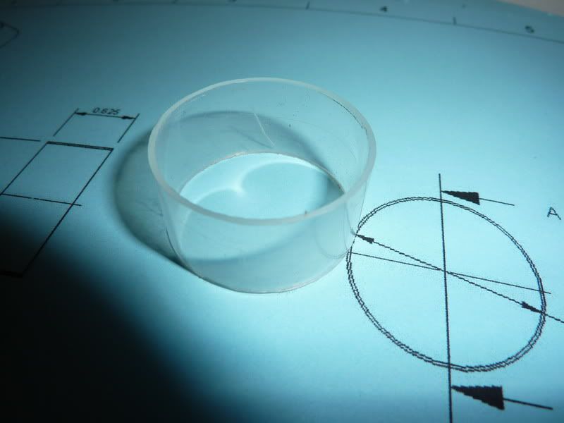
Next I cut the plastic tube to length, I gripped it in the lathe with a bit of nylon I found inside for support and parted it - worked fairly well, just needed tidy it up a bit with stanley knife, take little burrs off.

2010-12-0515-04-56_0003.jpg


Unfortunately it's probably not as clear as it appears in the photo, it also has picked up a scratch on 1 side. On the plus side, it is a really good fit on the little registers on top and bottom plate and is actually just about air tight with no sealant at all, but think I'll use something at least on the hot end.

Next I decided to have a look around for some material for the con rods - I couldn't really find much, I had designed it 1/8" wide x 1/32" thick. I found some 1/8" x 1/16" brass strip and thought this would do. The little ends have a slot in them 1/16" wide so there won't be any clearance there - will just have to make sure there is a little. The big end journals are 1/8" wide so plenty of clearance there.

This was the point when I had to double and triple check my dimensions as it all seemed stupidly small!

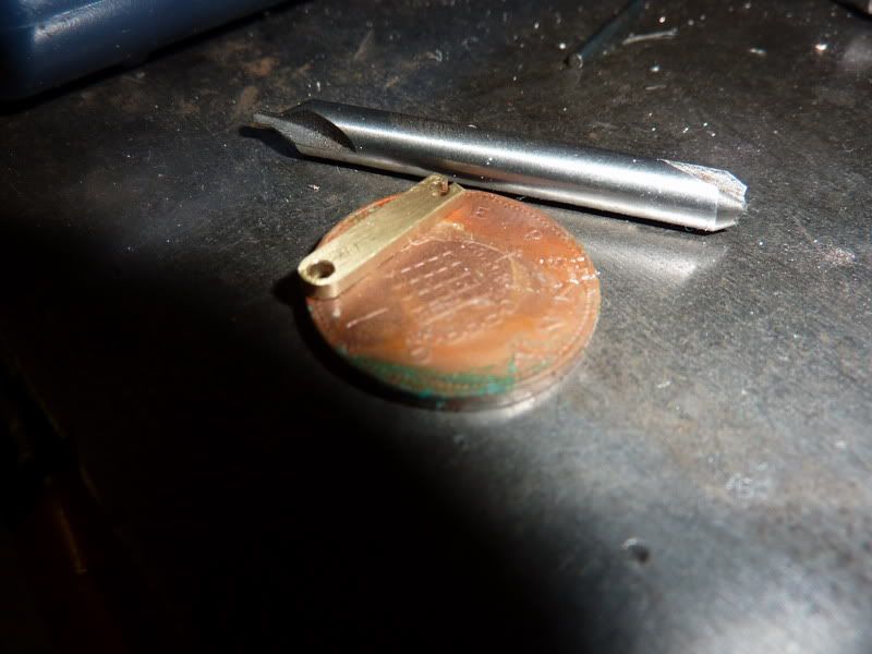
2010-12-0515-55-43_0005.jpg


That is the shorter displacer con rod, I have made the other too (see last photo). The only problem I see with these is whether I'll be able to get them over the crank or not - I was planning on turning that from solid. Hopefully they'll bend out enough to slip over then nip back with pliers. I annealed them before I made them to straighten them but may do again to be on safe side.

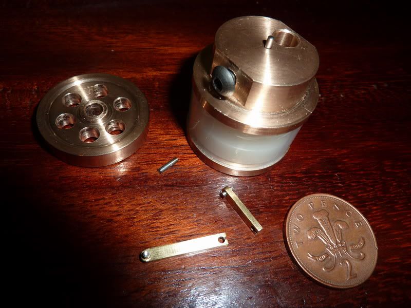
Here are all the bits so far:

2010-12-0516-33-08_0004.jpg


Still got uprights, all rods and pins (they are just cutting to length though), crank, displacer and pistons to do.

Nick
 
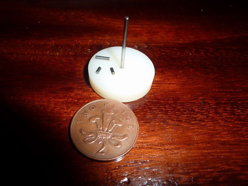
Still on schedule on this thing. Tonight I made the displacer rod, small end pins and a rod for the power piston as well as the displacer. The displacer was supposed to be made from balsa wood, but I didn't have any - I couldn't find a suitable piece of any other wood to turn it from either so I just thought what the hell - will try it from nylon, not sure whether it'll be suitable though - time will tell.

2010-12-0700-10-25_0001.jpg


2010-12-0700-16-05_0001.jpg


Nick
 
Nylon is fairly heavy compared to balsa and the engine has to lift the displacer against gravity every revolution of the crank. You may have to find some balsa (any model airplane supplier) or revert to a lighter plastic.
 
As Marv says Nick, the nylon is guaranteed to be too heavy.

If it helps, I used a thin sliver of building foam on my eggcup ones, and it worked a treat, it is very rigid and light even when cut down to 1mm in thickness.

When they are rebuilt, I have some very thin acrylic sheet that is going to make the displacers. I suppose on yours, you could even use margerine tub plastic.

This old post of mine might just help achieve what you need.

http://www.homemodelenginemachinist.com/index.php?topic=1510.0


John
 
Coming along nicely Nick. Your Dad will be chuffed with this for Xmas.

Cheers
Steve
 
Thanks Marv, John and Steve.

I did think it might be too heavy :mad: but I thought I might be able to balance the assembly by adding weight to one edge of the flywheel? What is building foam? I've got some quite dense foam but it's squdgie stuff, not rigid - will that be any good? Or is it not dense enough, does it hold on to too much air rather than moving the volume from one end to the other?

Either that or craft some sort of stand to make it horizontal and a sort of hot cap that transmits the heat to the base!! The friction on the displacer rod and piston would increase then though.

Nick

 
Adding even more weight to the flywheel to attempt to counterbalance an overweight displacer is not a good approach. This is especially true given that lots of lightweight materials are readily available.

Go to any artist supply store and look for foamboard stock - basically a thin layer of light, closed-cell foam sandwiched between two sheets of sturdy paper. Or use (styro)foam packing material. These foams can be "machined" using sandpaper. Fortunately, the dimensions of the displacer are not hyper-critical so caveman shaping is perfectly acceptable.
 

Nice work Nick. It will be great to see that little guy running.
 
True, good point Marv. Foam board - I've seen / used that before somewhere, should be pretty easy to come by. Actually, I was thinking of expanded polystyrene before (is that the same as styrofoam?) but thought it'd not be dense enough to shape into a decent piston - but it's given me an idea, at work we use quite a high density expanded polystyrene for packaging ammunition - I'll try to get some of that and show you, am sure there are a load lying around somewhere.

Once this thing is assembled for real it shouldn't really come apart so I need to get it right!

Nick
 
Remember that the displacer is not a piston - there's no need for a close fit to the displacer chamber. IIRC Jan allows for one millimeter clearance. The "machining" of the displacer can be done with less than watchmaking precision.

"Once this thing is assembled for real it shouldn't really come apart so I need to get it right!"

During the debugging phase of the engine you may want to think about sealing the hot and cold plates with something less permanent than adhesive. For the low temperature and pressures involved, vaseline will provide an adequate temporary seal and is easily removed for rework.
 
Another really interesting build Nick, keep up the good work!

Vic.
 
NickG said:
Oh no, why have I started another project before i've finished the previous two?

Masochist. Looking good.
 
Marv,

Yep, mine has about 1/16" clearance on my diameter - actually I think the nylon was about 5 thou undersize so it's got a bit more but should be ok it doesn't touch the sides and cant feel any resistance when the piston is on it's way down.

I may drill lots of holes in the nylon and sandwich it between 2 very thin layers of plastic - some food stuffs have this very thin vac formed stuff I could cut with scissors and glue to either end of the - or even just the bottom if I don't drill all the way through - could try with a slot drill.

Great idea using the vaseline - i have a feeling it may need to be removed. I can permanently attach the bottom cover though. Thinking about it, may not even do that though as I might end up soft soldering a metal tube in the middle if it needs some more heat!

Cheers Vic & Mike!

Nick
 
Nick,

Almost anything that is closed cell can be used, as long as it is not floppy when it is cut to thickness.

Expanded poly is usually a bit iffy with certain types of glue, it can disappear before your very eyes, but most others are usually inert. I normally use a dab of fast setting epoxy, that seems to work with everything.

Building foam is the light brown or blue stuff that builders use when insulating new builds. Go to a building site, and you can usually pick up pieces that have been cut out to clear joists etc. That is if you can find a working building site at this time, most have stopped because of the recession.

It is much lighter than balsa, but not quite as rigid.


John
 
Nick, I think I can get you a small piece of the blue foam. PM me if you're interested.

Vic.
 

Latest posts

Back
Top