Started the EZ_ENGINE build.

Home Model Engine Machinist Forum

Help Support Home Model Engine Machinist Forum:

This site may earn a commission from merchant affiliate links, including eBay, Amazon, and others.

woodknack

Well-Known Member
Joined
Nov 11, 2009
Messages
45
Reaction score
0
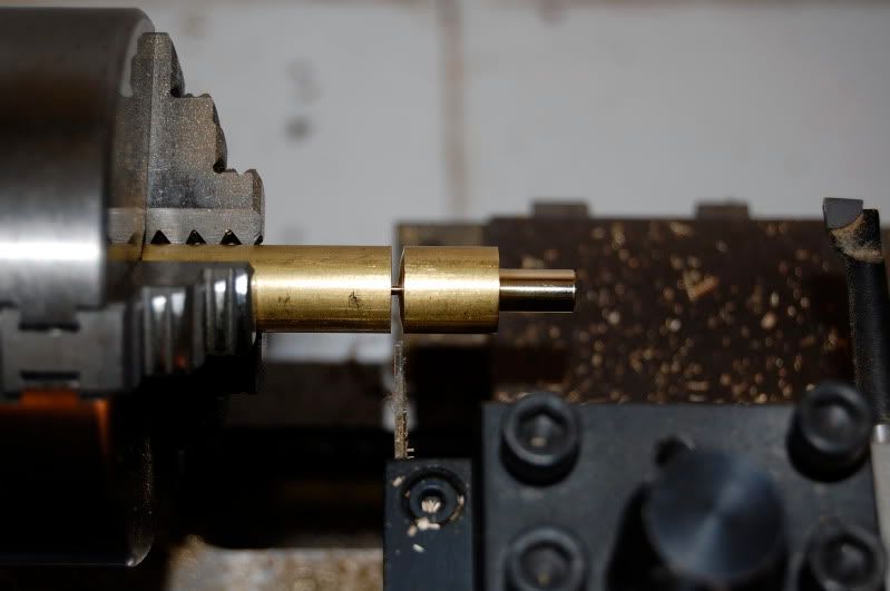
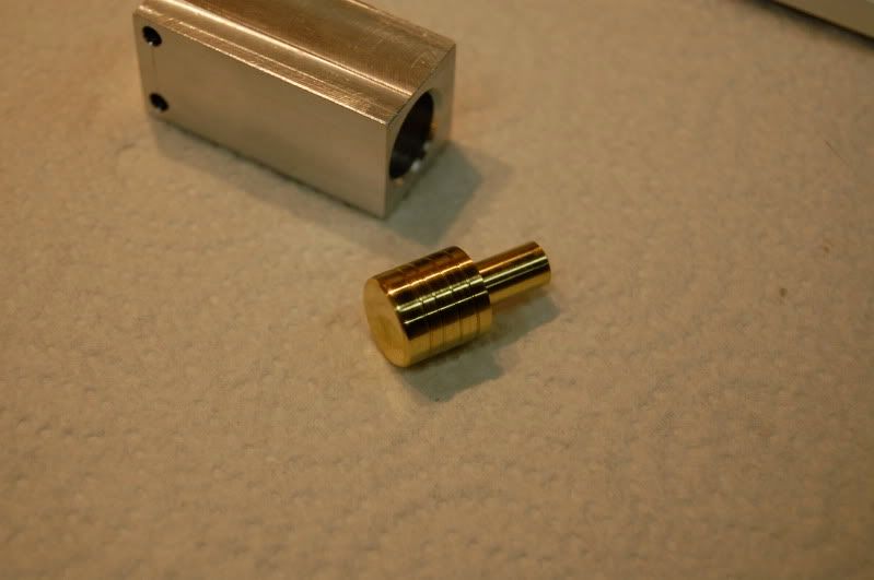
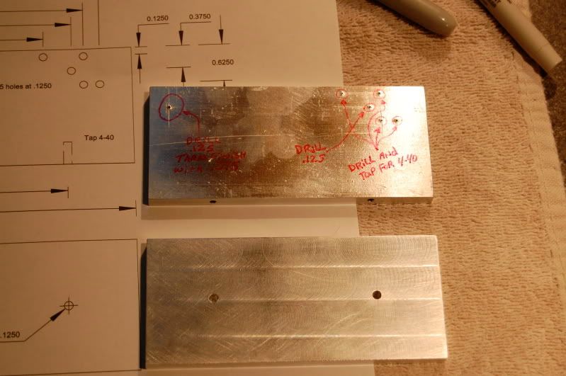
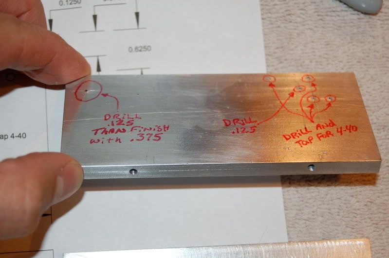
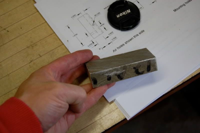
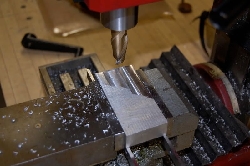
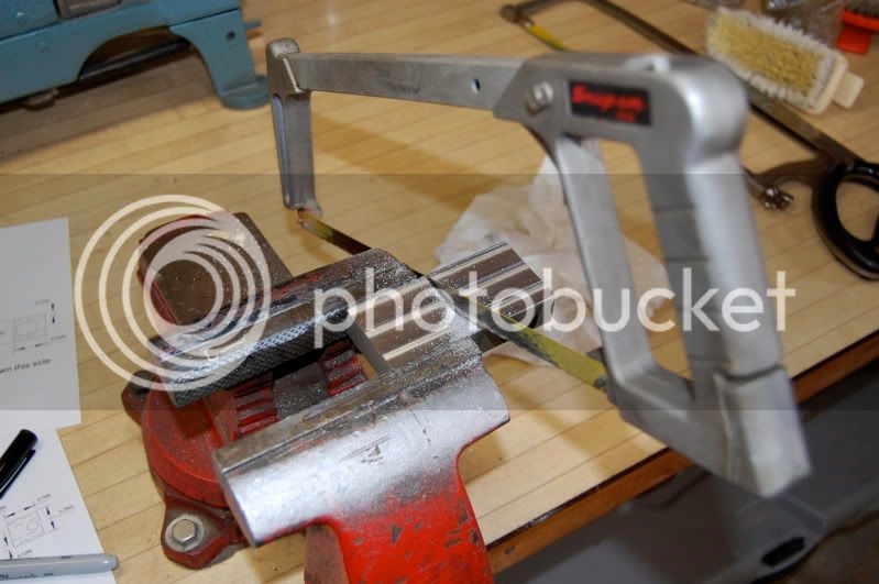
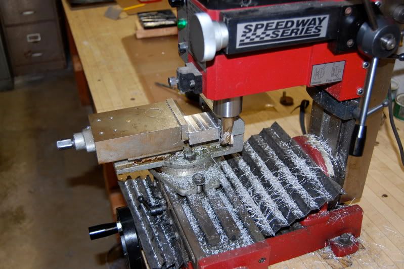
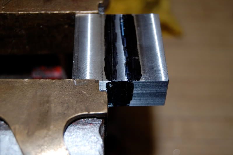
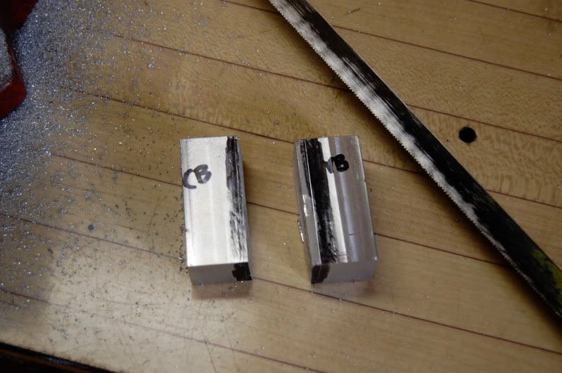
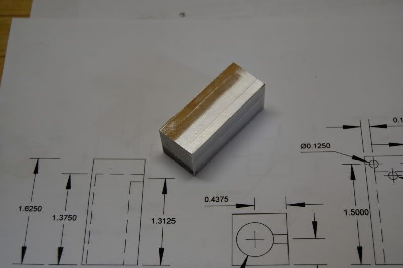
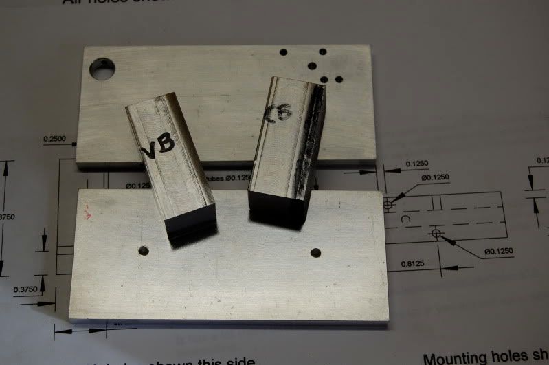
Well I figured I would try my hand at building the ez engine plus I like the design of it. I have made an easy wobbler engine, now I am looking for something with a little more of a challenge but not over my head. So I had the day off from work and I decided to look around the place for material and get started on this. I had a slab of 1/4 x 5 x 24 laying around so i took and hack sawed 2 pieces off for the base and the frame. I then spent some time truing them up on the mini mill. I got the base all drilled and the bottom of the frame drilled and tapped. Going to finish the other frame holes tomorrow and maybe start working on a cylinder.
DSC_0001-4.jpg


DSC_0002-4.jpg
 
Good luck on your build. I think getting started is the most difficult part. Jack
 
Off to a fine start. Thanks for the pics Thm: Not a bad idea to mark up the work so you don't forget which hole is which and do an "opps".
 
Ok did a little more work today. I found a hunk of aluminum that I could use for the valve and cylinder bodies.

DSC_0001-1.jpg


First thing I did was put it on the mill and planed it down to 3/4. The piece was a wedge shape another challenge for a noobie.

DSC_0002-1.jpg


After I cut it down to the thickness, I needed to hacksaw off a piece long enough for both cylinders. This is where a nice cut off machine would come in handy! But moneys tight so we do with what we have.

DSC_0004.jpg


I then squared up the hacksaw end on the mill.

DSC_0007.jpg


And put it back in the vise to hack it in half for both the valve and cylinder bodies. I had to be careful because I only had about 1/4 of an inch to cut between with the hacksaw.

DSC_0009.jpg


DSC_0010.jpg


Here is the valve body all squared up and ready for layout for the next step (drilling).

DSC_0011.jpg


And this is where I am right at the moment. Valve body all squared. The cylinder body needs to be squared next. The frame is all done drilled and tapped as well as the base.

DSC_0012.jpg


Excellent! Making do with what you have is right in line with the spirit of this project. Nice job getting the bodies cut and square.
 
Ok please tell me there is something wrong with the numbers here in the print. The 2 holes on the frame that the valve body screws to are .875 from each other. on the valve body print it shows the holes at .8125 . Which print is wrong? Or am I just having a stupid moment. :-\

DSC_0001-2.jpg
 
:wall: :Doh:

EDIT: Bad enough to make a mistake but to make another one while trying to correct the first is just too much! *club*
The information in this post was not correct.
 
ok thanks. i was thinking it was the valve body. i will plug the hole on the frame and re drill and tap. This actually made me set down and really study the plans. This is a great learning experience for me. Sometimes its good to sit back take a break and study your work. But sometimes I like to bull and had faith in the plans. Hopefully we can get all these bugs worked out so another noobie will be able to just concentrate on laying out measurements and trying to cut as close to them without worrying about something he or she is unsure of. See I am unsure of how this engine really works. Until I build it and see for myself then I will know. And next time it will be much easier for me to spot a mistake. This is great and I am glad you have spent the time to do this. Thanks again.
 
black85vette said:
:wall: :Doh:

Dang! A misplaced hole on the upright! Not too bad. The top left hole should be at 3.2" not 3.125". This puts the holes at .800" apart. The .8125" dimension on the valve body is measured from the edge of the body. The first hole is .125" in from the edge so the holes are .800 center to center.

Hmm im new to all this but.. if you subtract .125 from .8125 you do not get .800 center to center. you get .6875 center to center. Am I learning a little to fast here or and I having a stupid moment? LOL...
 
woodknack said:
Hmm im new to all this but.. if you subtract .125 from .8125 you do not get .800 center to center. you get .6875 center to center. Am I learning a little to fast here or and I having a stupid moment? LOL...

No, the stupid moment happened on this end. :Doh: I misplaced a decimal and the .125 became .0125. Anyway it still looks simple enough. The top left hole should be .6875" from the other mount point just as you pointed out. So that puts it at 3.3125" from the left edge of the frame. The valve body should still be fine.

Sorry for the error. Thanks for finding it. Karma point to you for starting the build and helping identify bugs.

See if the page below is better.

View attachment upright3.pdf
 
Black85vett,

Page looks a lot better. I see you fixed the 4-40 holes on the page too. ;) I mounted the valve body today But have not drilled the air intake yet because im not sure what I am going to use for a tube size. I started working on the piston cylinder today. I have to figure a way to mount it so I can drill and ream the cylinder in my mini mill. The vise I have in there does not allow me enough room so I may have to makes some sort of clamp to clamp it to the bed. Or I may just mount it in the 4 jaw chuck on my 7x12 lathe. Any ideas are welcome! So far a fun build. I just hope I can get it running on lung power like you did.
 
Good deal. Hope we are back on an error free track now. If you don't have room under the mill, I did mine in a drill press. However a 4 jaw is a great way to get a straight and square hole. Hmmmm, SQUARE HOLE???? ??? Seems like a contradiction.

What is the height issue with the mill?
 
The vise I have sits to high. and my reamer is pretty long. I think if i made some sort of a jig to fix the cylinder to the bed of the mill I would be fine. I really want to drill it and ream it with out resetting anything if I can.
 
My reamers were way longer than I would ever need so I cut them down so that there is just enough shank to hold it properly in the chuck. I cut mine off with a cut-off wheel mounted on my Dremel. I also use some stubby drills for much the same reason.
 
Got some more done today. I got so carried away I forgot to take pictures of the piston cylinder while I was cutting it out. But I did manage to drill and ream it. I had to make a jig out of 2 pieces of aluminum angle and bolt it to the piston cylinder then i was able to clamp the angle directly to the table. Worked great! I also turned down the piston too.

DSC_0007.jpg


DSC_0009.jpg


If I set the piston in the cylinder and let go it drops to the bottom. But if I put my finger over the air hole the piston slow starts to drop to the bottom and I do mean slowly. I can also blow and suck in the air hole (while holding my finger so that the piston does fly right out) and the piston moves very nicely back and forth with out much effort at all. This is all done dry to no oil. Im very happy with the fit. I think once oil get into the oil grooves it will be even greater. There were no drawings of the piston with oil grooves. I just put them about .100 apart and about .014 deep.
 
Hey Black85vette,

Does the piston valve have to be made out of steel? can that be made out of brass too? I have the steel but just curios if it can be made out of other material.
 
woodknack said:
Does the piston valve have to be made out of steel? can that be made out of brass too? I have the steel but just curios if it can be made out of other material.

Piston valve can be made out of almost anything, but I would not do it out of aluminum. Brass will work fine. In fact for those without a mill brass may be better because hand filing the flat for the connecting rod would be much easier.

Oil grooves are optional but a good idea. When doing oil grooves it is better to do them first and then turn the piston to size. Sounds like you got the piston perfect. Nice free fit but still has compression.

Parts are looking good and you are doing a nice job. Great photography also!
 
black85vette said:
Parts are looking good and you are doing a nice job. Great photography also!

Thanks! I have to give my camera the most credit for the photos (Nikon D40). LOL

Still playing with the cylinder and piston. LOL. If I drop the piston in the cylinder then cover the air inlet hole with my finger and flip the cylinder over, It takes exactly 4 seconds for the piston the slide back out. So far i very happy with this build. And she is starting to come together, slow but sure..
 

Latest posts

Back
Top