barnesrickw
Well-Known Member
- Joined
- Sep 8, 2012
- Messages
- 645
- Reaction score
- 121
Wood requires a bit of love. A bit fickle.
Sent from my iPad using Model Engines
Sent from my iPad using Model Engines


I cannot express how much I hate working with wood. But I think that's because I don't have the proper experience and skill to know how to persuade it to do what I want. Being a natural product, it's reaction can be frustratingly inconsistent and unpredictable. I find wood to be much too...um...disobedient.


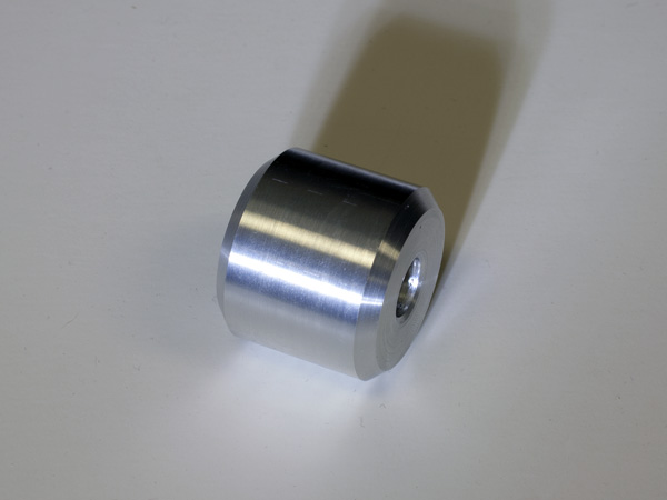
Well, I'm no longer a lathe virgin; I made my first part with the 8K. It's nothing impressive or terribly precise, but it does have a real use — it's a shock mount spacer for my project bike.

why the raised portions, rigidity?


I greased and oiled everything and did the preload procedure. Interestingly, I ran the rpms up a bit and warmed everything. There was a funny sound when I was warming it up, so I stopped and checked the spindle. Sure enough there was a little slop left in it, so I tightened the spindle lock down until there was no play and then backed it off again.
Well, I opened up the headstock and found my bearing packed with a white grease... maybe cosmoline?
I cleaned everything up with kerosene, put a little dte on everything and buttoned it up.
I greased and oiled everything and did the preload procedure. Interestingly, I ran the rpms up a bit and warmed everything. There was a funny sound when I was warming it up, so I stopped and checked the spindle. Sure enough there was a little slop left in it, so I tightened the spindle lock down until there was no play and then backed it off again.
After getting the pre-load done, I did the spindle break in. Everything went well and nothing got hot... just barely warm.
Finished up cleaning the apron and cross slide and got them installed and adjusted. Also put on the OXA QCTP.
Next up, I'm going to put the 4 jaw chuck on and dial the whole thing in.
I really like the fit and finish of the lathe. It's very solid and well-engineered.
Hope I can make some chips this weekend.
deek
Enter your email address to join:

