Snow Tandem Engine

Home Model Engine Machinist Forum

Help Support Home Model Engine Machinist Forum:

This site may earn a commission from merchant affiliate links, including eBay, Amazon, and others.
Dean: You're welcome!

Garry: The steady ring is 3.5" OD based on the scientific calculation of that's the dia of the scrap pipe that I had a piece of in my junk box... in this case, it was apparently some gas pipe, it was miserable to cut a chunk off with the Mk 1 hand-operated hacksaw. You could go up to 4" OD with a little room left for fastening over the bed of the lathe. Whatever floats the boat!

Joe
 

I just received my 4 issues with the plans so they had the complete set as of 2 weeks ago. Let me know if they dont have any more available.

Jason
 
Hi all

Next bit done already (I love statutory holidays... :D)
This is the piece that joins the two cylinder assemblies together. The turning was all done with the same set-ups as the front guard,once that was done bolted the whole thing together and then bolted it down on the mill to cut the openings in the sides
68c90aa5.jpg


and this is what it looks like in place
60d4afdc.jpg


Didn't have a really long M&M, so I put in a ruler for scale (sorry, Zee)

Cheers, Joe
 
It's looking sooo good, Joe. What a fabulous model.
It's getting big, too. (And thanks for the inches!)

Dean
 
That's some great work, Joe.
It's great to see work of this size being done on a Taig.
 
zeeprogrammer said:
Very nice Joe.
I had to take another tour through the thread.

Zee: Thanks, but didn't Mom tell you to get busy?

Ksouers & Dean, thanks for looking in, no problem about the inches, I'm an unrepentant Imperial measuring kind of guy.

Joe
 
joe d said:
Ksouers & Dean, thanks for looking in, no problem about the inches, I'm an unrepentant Imperial measuring kind of guy.
Joe

And why should you be "repentant", hmm? Carry on, northern neighbor!

Dean
 
Hi Joe, boy that thing is really starting to look neat. I saw one at NAMES last year and it makes an impressive engine.
gbritnell
 
Hi again

Northern neighbour here, carrying on as ordered.... (incidentally Zee, I'm not sure that I want to know if that was a philosophical question or what... )

George; thanks for that.

Got the crosshead done, the last of the big turning operations. Still the same set-ups as the previous two bits, except that it's finished with a taper.

Turned and bored the flange, turned it around in the chuck and turned the major dia of the taper for it's length and the minor dia for the rest. Bored that end out to near final size at the same time I had just removed the steady when I took this photo.
bafa85aa.jpg


set up the compound and turned the taper. If you look closely, you will see a 5 gal pail of swarf in the background... filled that twice doing these three parts!
3b13162b.jpg


Then turned it around again in the chuck, cut the internal taper, set it up in the mill (same as before) to cut the side cut-outs,
and here it is!
f7433d7c.jpg


Things will slow down back to normal speed now, no more 4 day week-ends for quite a while, dang it.

Joe
 
Hi all...


Moved forward with the crankshaft bearings.

Chopped up the raw stock in the mill
f1e2fff0.jpg


after milling 5 sides for squareness, bored the through hole and started shaping. I don't have any ball-end mills or corner rounding ones, so dug out the woodworking carbide router bits, worked just fine
d40b27d9.jpg


drilled the mounting holes, then cut one end off to be the second bearing, cleaned everything up, turned some bronze bushings and here we are
b02bf757.jpg


Finally got the stock for the rocker arms, so will get stuck into those next. Fairly complex little bits, so it will take a while I suspect.

Cheers, Joe
 
Joe;
With the Taig's what depth of cuts and feed rates have you found best for the carbide router bits and the Mastercraft saw when working with aluminum or brass? Fairly light cuts I assume but how light?
What tooth count was the Mastercraft saw?
Is there an upper limit to the radius on the router bits that you've found - too much cutting edge / not enough power? I.E - how large a router bit have you been able to use?

Cheers
Garry
 
Doggonnit, I missed your Jan 4th post, somehow. The engine assembly is so impressive, Joe. I love this thing!

Those bearing blocks are really nice. A very pleasing contour to them. The router bit worked well, and you did a good job.
Have to look into those router bits.

Dean
 
Hi Garry

The saw blade is 85mm dia 24 teeth, they stock it as a replacement blade for their laminate trimmer. I run it at around 2k rpm, mounted on a standard Taig arbour I have just under 1.2" of blade before fouling on the arbour. It pretty much lets me know when it's not happy, then I just slow down my feed rate a little. As I don't have power feed, it's hard to quantify: I just crank a little slower. A frequent squirt with WD40 makes it better through aluminium, although it's hard on my shirts.... the biggest issue to date is looking out for the off-cut going flying when you've cut through.

With the core-box router bit (Ball end to the machinist) and the round-over, I ran at around 3k rpm, was taking 20 thou cuts with no trouble conventional milling, this was leaving some chatter marks that came out by just going back (climb milling) with no additional depth put on for the final pass. The 3/8" round-over is the largest I've tried so far, this particular one is over 1" in dia so it's a fair weight of metal behind the cutting edge.

I'll have to go through the collection of bits in ever increasing size one day just for the heck of it to determine what is the max size I can realistically use. I have quite a few bits in 1/4" shank which snug up nicely in the collet on the mill.

Cheers, Joe

PS Dean: You popped up there while I was typing: thanks.
 
Thanks, Garry

You're right, I am usually up fairly late.

Those mods for the lathe just keep on piling up :big:

I need to build the ball turning attachment as well so I can do those nice locking screws too, get rid of all those cap screws, convert the little brass handles on the various feeds to spinning ones, add a lead screw... this thing is going to keep me busy for a long time!

Cheers, Joe
 
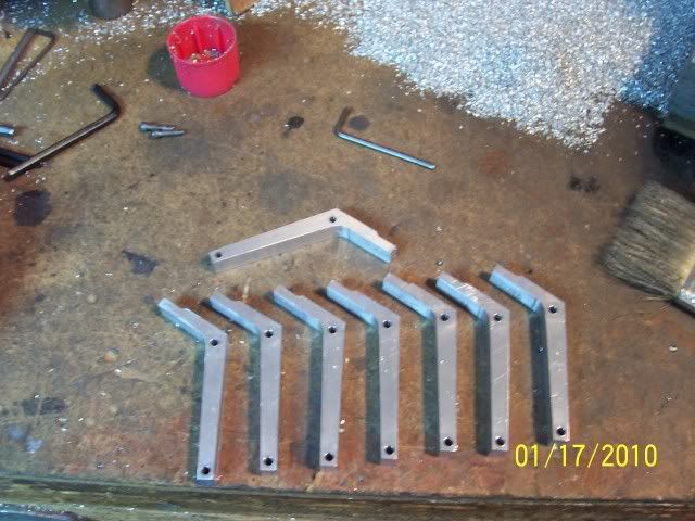
Well, finally got started on the rocker arms. Happily, there are two holes called out in the same plane, so I could use them for locating virtually everything. Did all the lay-out, drilled the holes, cut out the blanks, and went to work on a sacrificial plate on the mill with a series of tapped holes to hold the parts in the various orientations required.
100_2411.jpg


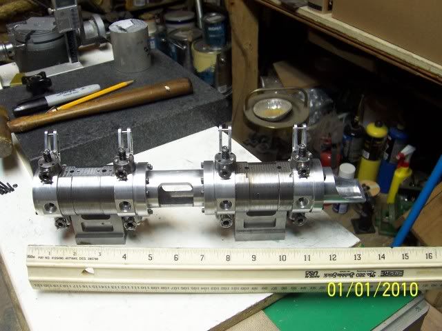
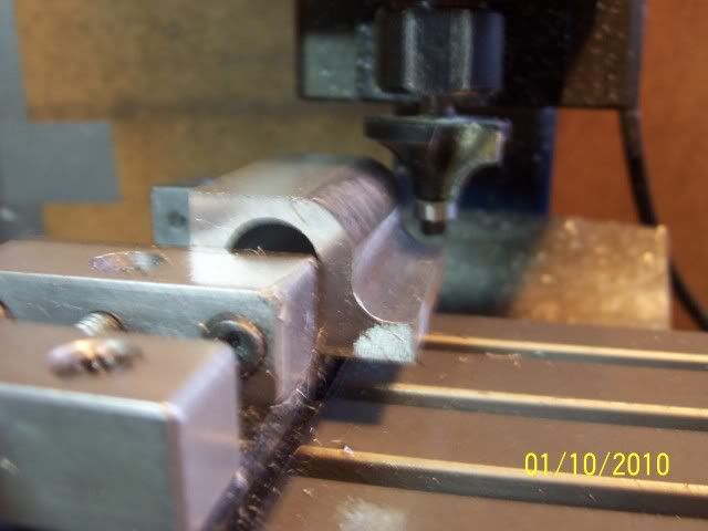
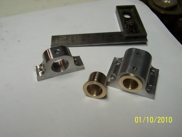
you can see the marks left from milling the long sides, and using a .5" end mill for the inside radius. A lot of repetitive motion, and here the are all done with the fixture for now.
100_2413.jpg


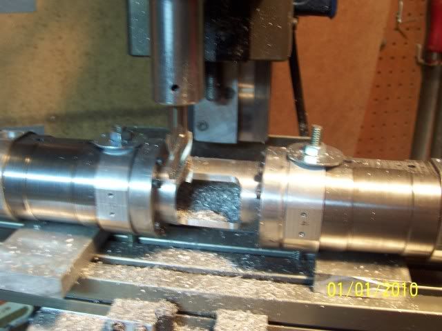
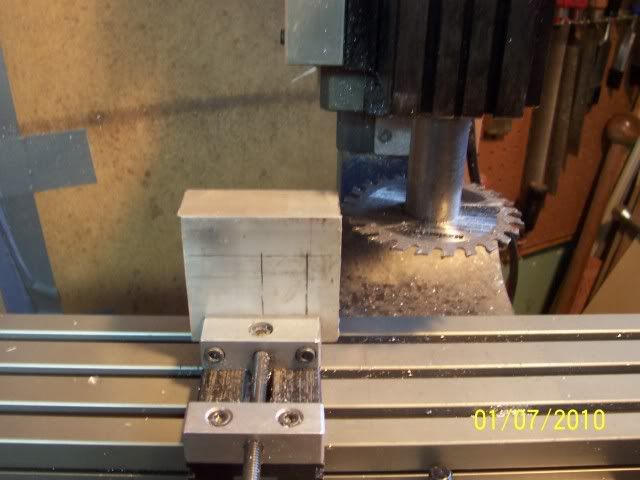
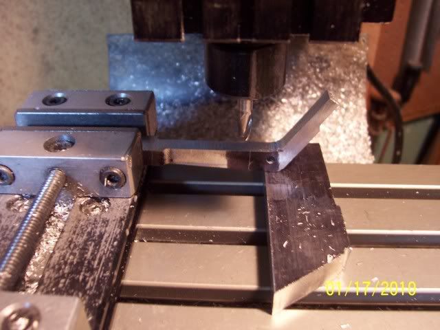
Couldn't think of any really good way to hold the parts for milling the sides down to dimension, so did them pretty much hanging out in the air, light cuts and easy feed, and happily, no drama.
100_2414.jpg


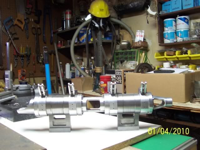
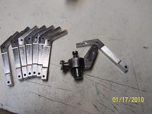
and here's where I am so far.
100_2416.jpg


Still got some rounding over to do, cut a slot for the cam follower, drill and tap a hole for the screw that actually moves the valve, and another visit to the fixture for milling some decorative reliefs on the sides.

Cheers, Joe


Latest posts

Back
Top