Small V8

Home Model Engine Machinist Forum

Help Support Home Model Engine Machinist Forum:

This site may earn a commission from merchant affiliate links, including eBay, Amazon, and others.
Hey Jim,
There will always be someone better. Anyone who makes something with his own hands should be proud of it. At least we can look back at the time spent 'here' and say we accomplished something.
George
 
Steve, this is looking great. What an ambitious project.

When you say how long some part has taken I have to read it twice, you get things done so fast.

Lee
 
LeeScrounger said:
When you say how long some part has taken I have to read it twice, you get things done so fast.

Thanks Lee!

Doesn't seem all that fast to me. If you go back to the first page, that was 10 months ago. Hard to believe that much time has gone by. I gave myself a year but somehow I think I'm going to be a little more than that.
 
Beautiful work on this engine, Steve. Can't even begin to imagine how much time you've spent on some of the small, intricate parts. You truly have a way with metal. I really like your work.

Chuck
 
cfellows said:
Beautiful work on this engine, Steve. Can't even begin to imagine how much time you've spent on some of the small, intricate parts. You truly have a way with metal. I really like your work.

Chuck

Thanks Chuck! Now that NAMES is over I can get back at it.
 
Great looking engine well done :). Regarding the crack, at which rpm did you machien it and as for the tool you used hss right?

Drei
 
GDay All,

Stevehucks396, I hope you have been able to find the time to put the finishing touches on your excellent engine.

Some time ago, you commented that you would like to see my engine design, so I have added some screen pics of my 3D model.

I hope you don't mind, but I changed my carburettor float bowls to resemble yours. That was one element of my design that I didn't like and yours looked so much better I just had to copy them. Sorry about that.

My engine is, and has always been intended to go into an RC model. Either a car or a boat, hence the inclusion of the starter motor and manual clutch.


Engine - V8 MK5 - Carbs - 01.png


Engine - V8 MK5 - Carbs - 02.png


Engine - V8 MK5 - Carbs - 03.png


Engine - V8 MK5 - Carbs - 04.png


stevehuckss396 said:
If you go back to the first page, that was 10 months ago. Hard to believe that much time has gone by.
I gave myself a year but somehow I think I'm going to be a little more than that.


What does it matter? The amount of education that you have gained, from your experience, and the extensive amount
of edification that you have been able to impart, especially to those who have been watching your progress, has been priceless.​
 
trumpy81 said:
I hope you don't mind, but I changed my carburettor float bowls to resemble yours. That was one element of my design that I didn't like and yours looked so much better I just had to copy them. Sorry about that.

My engine is, and has always been intended to go into an RC model. Either a car or a boat, hence the inclusion of the starter motor and manual clutch.

I don't mind at all. Looks good. Hard to get a feel for how big it is.

Cooling in an RC car would be a problem. If I redesigned the cooling system just a little, I think mine would work well in a boat. The constant supply of cool water in the boat would be the only way.


Heatherrose said:
What does it matter?

To me, it doesn't. It will be done when it's done. I know there are some folks out there that want drawings so i'm trying not to drag it out but i'm not rushing it either.
 
stevehuckss396 said:
I don't mind at all. Looks good. Hard to get a feel for how big it is.

Cooling in an RC car would be a problem. If I redesigned the cooling system just a little, I think mine would work well in a boat. The constant supply of cool water in the boat would be the only way.

GDay All,

stevehuckss396, You're right, I should have included a scale of some sort, would've been easy enough to do. Anyhow, here are the specs for this engine.

Bore & Stroke = 17.5mm (0.688 in) x 15mm (0.590 in)
Overall Length = 202mm (7.952 in) From front crank pulley to end of drive shaft
Overall Height = 139.812 mm (5.505 in) From sump plug to top of air cleaner
Block Length = 104mm (4.094 in) From gear case to rear of block
Cylinder Head = 99mm (3.898 in) x 30mm (1.181 in)
Ignition = Points + Transistor + Coil + Rimfire Micro Viper Z3 spark plugs.
Distributor = Dia. 25mm
Fuel = Methanol, 5% Nitro.
Throttle Bore = 5mm
Starter Motor = 12v - Dia. 35mm x Length 62mm.
Bell Housing = Dia. 65mm (2.559 in) x Length 48mm (1.889 in)
Clutch = Single plate.
Water Pump = Impeller, block and cylinder heads are water cooled.
Lubrication = Wet Sump, Splash feed, although I am still working on a dry sump system with external oil pumps. All oil galleries are present, including the crankshaft, but getting the oil in has proven more difficult than I first thought. There's not much space left in the block for much of anything ... lol.
I'll crack it though .... lol

I hope to start building at the end of this year, but first I need to complete my Triumph 650 Bobber.

As for your engine in an RC car, one way would be to include two or more radiators and computer type fans. It shouldn't be too much of a problem, after all the Connelly V8 doesn't have water cooled heads and it seems to do OK in RC cars.

Your engine in a car would look super cool!!, or on a scale engine stand or a mockup dyno test rig. Of course that means more work, but then, this is a hobby hey ... lol

I'm looking forward to video of the engine running, but I know you have more pressing matters to attend to first. No hurry.

And thank you for inspiring me to continue with my life long dream of building a model V8 engine.


I wanted to know how did you time the engine, for example which the firing order and thus how do you number the cwlinders. I mean do you start counting on the crank shaft or on the cylider bancks and if so after each other or crossing them?

Then as for the cam timing, once you have determind the cylinders firing order and numbers how do you time the cam lobes for every individual cylinder? Is there any specific method?

In short words, if i had to design and built a v8 engine how would i get the correct timing?

Thanks Drei
 
GDay All,

Drei, the camshaft timing depends on a lot of variables, for example, it depends on the direction that the crankshaft rotates and also the throws of the crankshaft as well.

In my engine, I cheated a little because I copied a 350 Chevrolet crankshaft, so my camshaft timing and cylinder numbering are the same as a full size 350 Chevrolet engine.

You could also use a Ferrari, BMW, Mercedes Benz etc. to get the same type of timing information and layout for your crankshaft, regardless of how many cylinders the engine has.

Your local auto mechanic should be able to help you with all the information you need.

I hope that helps :)
 
Thanks for the information andy. How did you copy the Chevy crank and timing, did you use any prints and if so how did you got them:

Drei
 
GDay All,

Drei, I didn't use any prints, only photographs. There is no need to copy all the dimensions, just the layout.
 
Drei said:
I wanted to know how did you time the engine, for example which the firing order and thus how do you number the cwlinders. I mean do you start counting on the crank shaft or on the cylider bancks and if so after each other or crossing them?

Then as for the cam timing, once you have determind the cylinders firing order and numbers how do you time the cam lobes for every individual cylinder? Is there any specific method?

In short words, if i had to design and built a v8 engine how would i get the correct timing?

Thanks Drei

Hello Drei!

I started with the most common layout for an american V8. Cylinder closest to the front of the engine is #1. I put that cylinder on the driver (left) side like a Chevy. 1,3,5,7 down the left side and 2,4,6,8 down the right side. I also copied the Chevy firing order of 1,8,4,3,6,5,7,2.

I have a method for doing that. Read this article and see if you understand how to lay out the lobes. It is a bit confusing, I had to read it twice and I wrote it. Page 7 has info on laying out the lobes on the sheet. I just emailed it to you.

The hardest part is choosing a lobe shape. Once you know the lift and duration you want to use, figuring the rest is not to bad. I like 280 degrees with 60 degrees overlap for my carbed V8 and 300 diration with 80 degrees overlap for my blown engine. Simply because I like how the cam sounds. Far to many model engines are under cammed. I don't know the reasoning behind it.


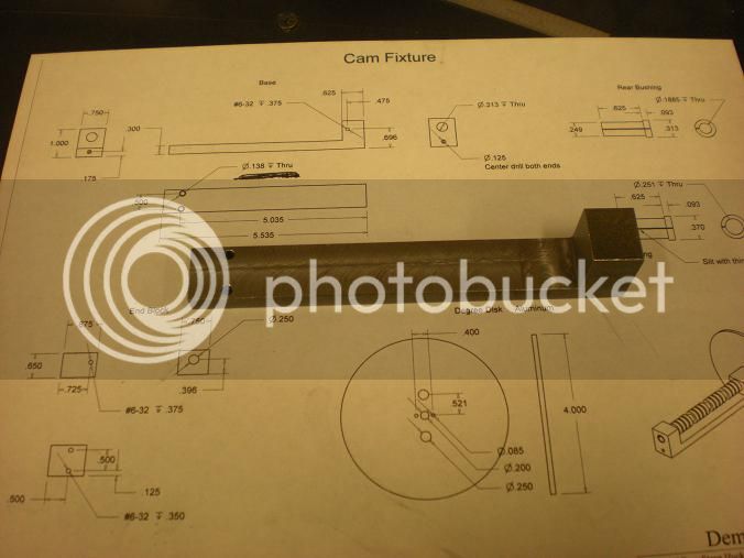
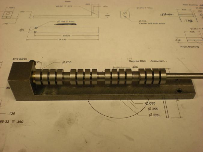
Well I finally found a minute or two today so i picked up where I left off on the cam fixture. I drilled the holes in the base that the end piece bolts onto.

DSCN1704s.jpg


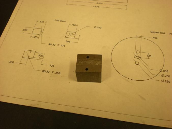
Then the end piece was made and the holes were drilled and tapped.

DSCN1706s.jpg


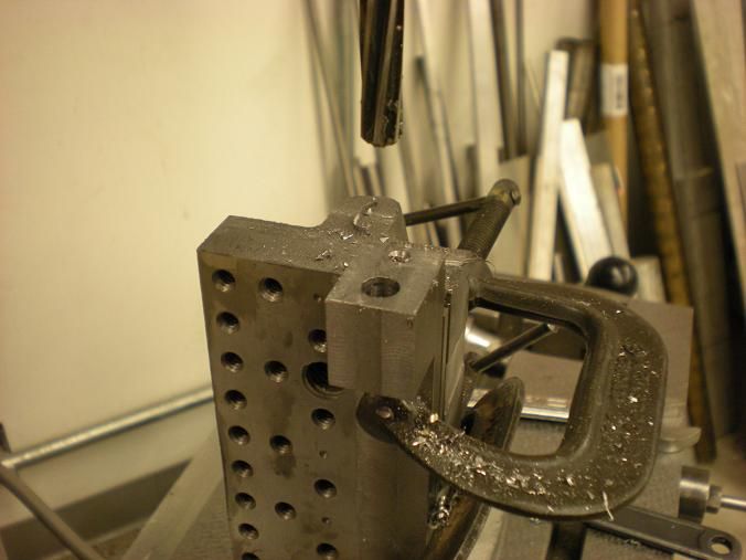
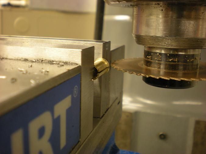
The fixture gets bolted together and clamped so the ends can be drilled. I like to do it this way so I have a better chance of the 2 holes on different pieces being the correct distance center to center. The centers are drilled and the holes for the bushings are drilled and reamed. Then the holes are drilled for mounting the disk.

DSCN1708s.jpg


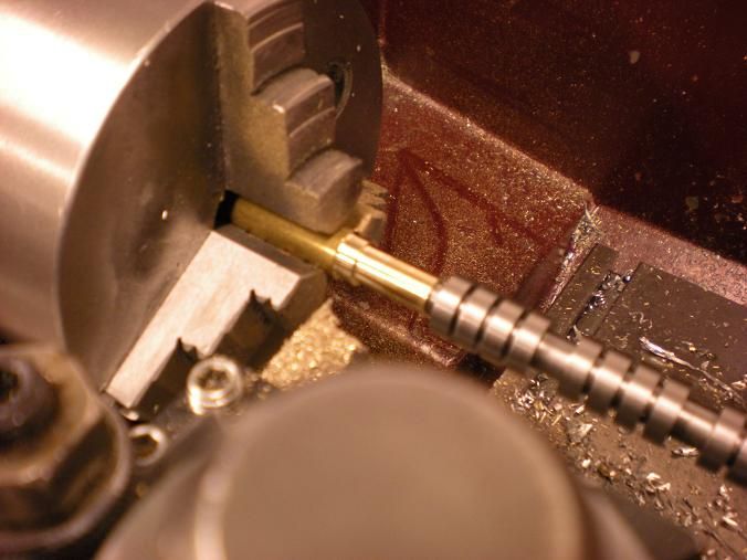
After the fixture was finished I made the 2 bushings that keep the shaft safe from the screws.

DSCN1723s.jpg


DSCN1724s.jpg


The cam gets installed into the fixture. Set the bushing so the slit is straight up. This way if they spin while machining the shaft you will notice.

DSCN1727s.jpg


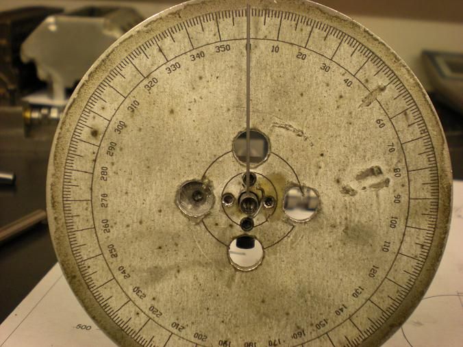
The rear piece goes on and the fixture is bolted together. The disk is installed and the pointer is slipped thru the hole in the cam and curled around the shaft. Screw the set screws in that lock the cam in place. Tighten the heck out of them to create a divot in the side of the bushing. Now when you loosen the screw to turn the shaft the bushing should stay in place and not rotate the shaft. When you glue the degree wheel on the disk try to have the zero mark dead left with 90 degree straight up. This way you can start at zero. I doesn't matter where you start but it is nice to start at the beginning. Set the pointer at zero degrees and the shaft is ready for lobes.

DSCN1734s.jpg


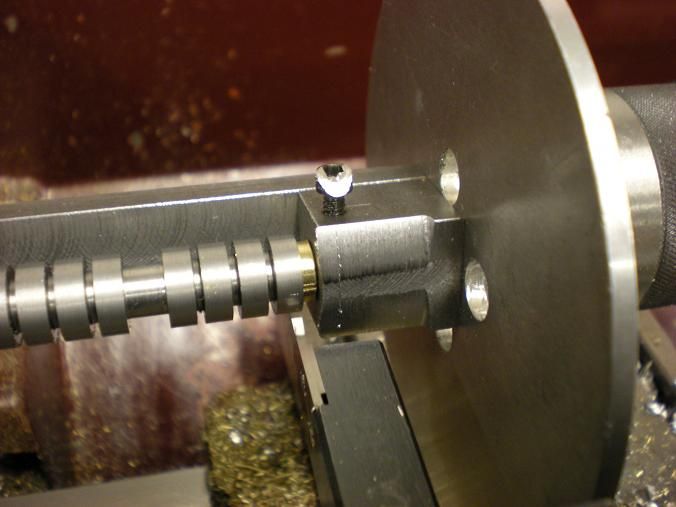
I put the fixture in the lathe to check for clearance. Glad I did because the tool was catching the top corners of the fixture. I turned the fixture corners and rechecked again. Everything looked good and I could move the tool everywhere I need to without a crash.

DSCN1736s.jpg


As a final check i butted the tool into the cam on the front lobe and the dial stopped at 21. Then I moved to the rear lobe and did the same and the dial stopped at almost 22. This tells me the shaft is aligned to the lathe by less than .001. All my lobes should have the same lift if I stop at the same place on the dial.


Now I need to find 4-5 hours to machine me some camshaft.
 
Doing your V8 cam that way is quite an undertaking! I did a four cylinder cam that way a number of years ago and don't remember much about it now but there is something about it that didn't leave good memories. It was made for a reduced sized Mastiff flat four that was modified to be air cooled so the tappet angles were different so all of the 'plan' layouts were not applicable... I found that even with the four cylinder, that the cam flexed as the center lobes were nipped away and in that thinking I would place a half support at the center of your frame.

Just a suggestion in good humor and knowing that you know what you're doing....Maybe I'm too careful.

Good going there man! We are following intently! I'm pretty lame about the number of parts involved with a V8 - I hate 'mass production'!

BillC
 
BillC said:
I'm pretty lame about the number of parts involved with a V8 - I hate 'mass production'!

Hello Bill

Try 2 V8's at the same time!

Not to worried about the flex. The smallest part of the cam is still .300 diameter. When I cut a lobe for the first time I cut .005 at a time until I get to .070. Seems lite alot of cutting but they go quick because you can see where to stop. So zip zip zip zip for the first cut. When rotated for the second cut its about .015 to .020 on the next so they go even faster. My V4 took less than 4 hours. This one should be around 5 hours.
 
Hi Steve
It looks amazing :bow:
would u please post a wider angle pic, showing the fixture in the lathe ,Im not sure I understand how it works :)
Pete
 

Latest posts

Back
Top