Rupnow i.c. Engine with governor

Home Model Engine Machinist Forum

Help Support Home Model Engine Machinist Forum:

This site may earn a commission from merchant affiliate links, including eBay, Amazon, and others.
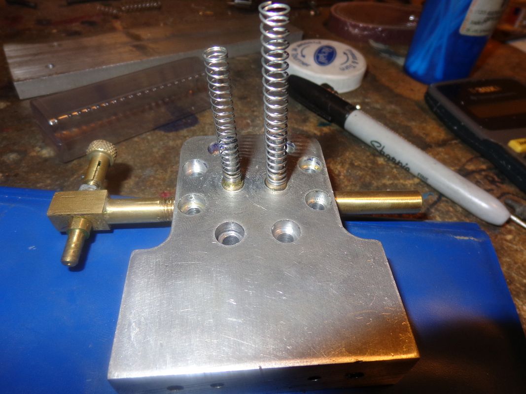
Choosing valve springs for these small engines is always kind of a crap shoot. I generally try and get a spring closest in size to whatever I used on the last engine I built. In this instance, the intake valve spring I chose is made from 0.012" diameter wire, has approximately 13 coils per inch when spring is "relaxed" and will just fit over a 3/16" drill. Since there is no cam to operate the intake valve, the spring must be very light to let atmospheric pressure open the valve when required, yet strong enough to close the valve against any friction in the valve guide/cage. Consequently, the valve must move very freely in its guide. Once the valve is closed and the piston starts to come up on compression stroke, the internal pressure will seat the valve even tighter if everything is working properly. The exhaust valve spring is 0.024" wire diameter with 10 coils per inch when the spring is "relaxed" and it too will just fit over a 3/16" drill. The exhaust valve has a mechanical cam to open it, so the spring can be stronger. In fact, it has to be stronger, because not only does it have to close the valve, but indirectly it also moves the rocker arm and the lifter mechanism, and holds the bearing on the end of the lifter mechanism firmly in contact with the cam. The exhaust valve spring as purchased is 2" long. I will probably cut it in half and start out with a spring 1" long, but that may change depending on the operation of the engine. The intake spring is 1 1/2" long, and I will probably cut it in half as well. I purchased my springs at Brafasco in Barrie. Fastenal is another fastener company that has a selection of springs.
 
So that's it for the valves and springs. A good sign is that with the pressure of the springs alone holding the valves in their "seated" position, I am unable to blow any air (lung pressure only) through the exhaust pipe or the carb air inlet. The exhaust valves don't generally give too much trouble, because the stronger spring ensures a pretty good seal. The intake valves though, can be a real bear, trying to find a happy balance between a strong enough spring to seat the valve, but yet weak enough to open under atmospheric pressure.
 
Well, its all back together. No disasters, no surprises. (Well, I was a bit surprised at that blob of green Loctite on the exhaust pipe.--I didn't see that before I took the picture). I have compression. Question is, do I have enough? I haven't timed the valve train nor the ignition yet, but I'm tired. I will save that for tomorrow. The last time I built an engine, a far more experienced fellow than I am said to not worry so much about compression on a new engine. He said to hook up the gas line, hook up the coil, make sure everything is timed properly, and then drive it with an electric motor until it "catches" and begins to fire and run on its own. Once the engine has fired 10 or 20 times, the force of the pressure created by ignition will cause the valves to seat completely. I may try that approach tomorrow.
 
NOW---Is the time for everyone who was concerned about me "building too fast" to catch up to me. Everything is built as per the posted drawings. This next stage is the truly dreadful, frustrating part of small engines.---Getting to "First Fire". Once you can get these things to fire, they will invariably run. This is my fifth i.c. engine. I started with a Webster 5 years ago.---Biggest thrill of my life when that thing fired up and ran on its own. Then, emboldened by my success, I built the Kerzel hit and miss engine. I had always heard of "Hit and miss" engines, but until I built the Kerzel, and did a ton of reading, I never really understood what the term implied. I have posted all of the builds of these engines here on HMEM, and anyone who takes the time to hunt them up and read thru all of the pages can feel the frustration I met getting those engines to run. I built the Atkinson engine just because its such a weird engine, and I wanted to see if I could build one and run it successfully. It does run, but its such an unbalanced temperamental tool of an engine that now I wish I hadn't wasted my time with it. The Odds and Ends hit and miss engine was built with one thought in mind. I wanted an engine of sufficient displacement to run the sawmill I had designed and built. So---All of you brave souls who thought it might be fun to build my latest engine---now you can catch me. I will be out in the main garage pulling out my remaining hair trying to get this engine started.----Brian
 
So far, nothing has been said about setting up the engine to run. I have just went through it all, and while it is still fresh in my mind I will cover it off. First, lets start with the exhaust valve adjustment. You will see that the push rod mechanism is made in two pieces, with the 1/8" threaded round section screwed into the end of the 3/16" square section, and locked in place with a jamb nut. After everything is assembled, turn the engine over until the cam follower bearing is on the side of the cam opposite to the high "lobe" end. Adjust the length of the pushrod so that there is about 0.010 of "freeplay" between the end of the pushrod and the recess in the rocker arm, then lock up the jamb nut. This "freeplay" ensures that the valve will not be held open with a consequent loss of compression during the compression cycle of the engine.
 
Last edited:
Nice work Brian.....can't wait for the video of it running.

Andrew
 
Wild and crazy day here yesterday!! Black sky, torrential rain, tornado warnings on all the radio stations with a couple of " Take Cover Immediately---This is Not a Drill" broadcasts. Momma had the grand daughters down in the basement a couple of times when the house started to shake. I kept working in the big garage with the door open---Thought maybe I'd get to visit with Dorothy in Oz!!! Nothing tragic happened. Lost electricity a couple of times, lost internet for most of the day, had a few rotten branches come down on the yard. Have a lot of news to post about the Rupnow Engine today, now that power and internet is restored. Sun is shining, humidity is broken, Granddaughters have fled home to their mom and dad. More posts with pictures, videos, and "how to" articles to follow.---Brian
 
Okay--First a few still shots and explanations. The first picture is a "good news" shot---The water Reservoir.-I filled it with water before I went to bed---This morning it is still full to the top. This seems to prove that my o-ring seals on the water jacket work fine. Also in this first pic you will see where I chose to mount the condenser. This was a last minute decision, as I hadn't made provision for it on the 3D model. I drilled and tapped the sideplate for one #5-40 unc capscrew. It will not interfere with the "latch" mechanism from the governor. In the second picture you can also see the brass bushings I made and installed in the holes which I put in the wrong place for the governor cross shaft--I drilled them out oversize and Loctited the bushings in place. The hole in those bushings is undersized, and they will be reamed "in situ" when I get to that part of the build. Rather than spend a week disassembling and reassembling the cylinder head to get a "perfect" airtight seal on the valves, I took advice from I believe it was Jim Dunmyer but I could be mistaken and hooked up the engine to an electic motor with a v-belt, wired up the ignition and plumbed the gas tank, and let it run. At first the compression was rather anemic, because even though the valves sealed perfectly with "lung pressure" as covered in previous posts, they leak a bit when subjected to full engine compression. I fiddled with the carb jet until the engine began to fire consistently, and let it run that way for an hour. (I kept squirting #30 oil into the back end of the cylinder occasionally to lubricate the piston and ring, as I haven't yet installed the oil cup for the cylinder.) After an hour of running, the compression during combustion in the cylinder had seated the valves to the point where the compression had improved dramatically. I shut the electric motor off a couple of times, but the mechanical disadvantage was too great. The engine wanted to keep on running, but didn't have enough "oomph" to turn the armature in that old 1/2 HP bale elevator motor.


That looks and sounds awesome Brian you've done a fantastic job of the engine.

James.
 
Verry nice work Brian anxious of getting mine running
Ill be posting many pics of finish stuff this week end.

While I was watching your video I notice that the spark in your point
is pretty erratic, maybe you should have a look

cheers
 
Here is a set-up shot for Path. In this shot the engine is setting on 123 blocks with the end of the crankshaft held in the vice. It has just been drilled for a 1/8" cross hole to accept a 1/8" diameter x 3/4" long roll pin which my "starter" engages.
 
Here is a set-up shot for Path. In this shot the engine is setting on 123 blocks with the end of the crankshaft held in the vice. It has just been drilled for a 1/8" cross hole to accept a 1/8" diameter x 3/4" long roll pin which my "starter" engages.

Thanks Brian ... ;);)

Pat H.
 
Magnificent Brian, a real credit to you, sounds so sweet.

Andrew
 
Magnificent Brian, a real credit to you, sounds so sweet.

Andrew
I've got a ways to go yet. It has to run pretty well perfect as a normal 4 cycle engine before I can go to the hit and miss version. I am amazed at how much compression it has. Right now its doing something funny that I have to chase down. It starts perfect, runs for about a minute, then staggers and quits. I don't know if its running out of fuel, or getting too much fuel. I am thinking it is carburetor, not spark. Tomorrow morning I will put my store bought Traxxas carburetor on it and if that cures the problem, I'll know there is a problem with the carburetor I designed and built. If that doesn't cure the problem, then I will look at ignition issues. This is always the time consuming part of these small engines.--Getting them to run flawlessly after they are all assembled.
 
At least all the hard work is done, time now to pull your hair out fine tuning!

Couple of questions, what type of spark plug are you using and what fuel mix?

Andrew
 
Sparkplug is an NGK CM6---It has M10 x 1 metric thread. I burn Coleman fuel (Naptha gas) with just a dash of 2 stroke oil to keep the piston lubricated.
 
Carburation, ignition, or something else. Yep, that pretty well covers it. I haven't posted the valve timing sequence yet, but I will. My first attempts at starting the engine were semi-successful, but I couldn't get a run of more than 10 seconds duration. I thought "I bet I'm out one gear tooth on the valve timing', so I undone the crank bearing bolts enough to move the gear train one tooth from where it was. That immediately yielded the run you see in the video.
 

Latest posts

Back
Top