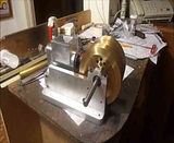
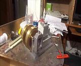
Alright--I have finished the water cooled cylinder, the water reservoir, and the the water reservoir retaining ring. They were a little more involved than I had first thought they were going to be, but not bad.--Just a lot of hours. --So--Herewith are the associated drawings.---Brian
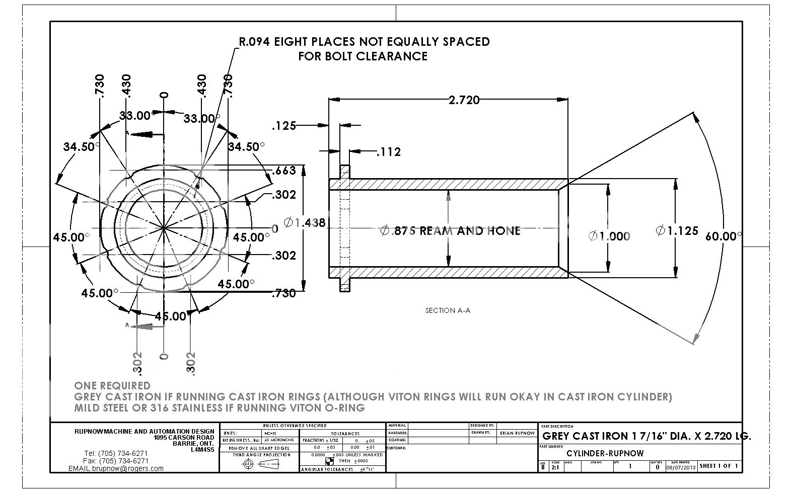
View attachment CYLINDER-RUPNOW.PDF
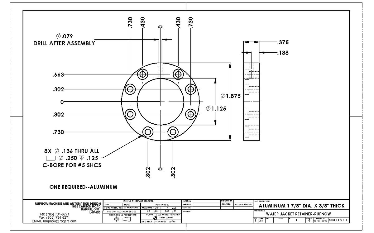
View attachment WATER JACKET RETAINER-RUPNOW.PDF
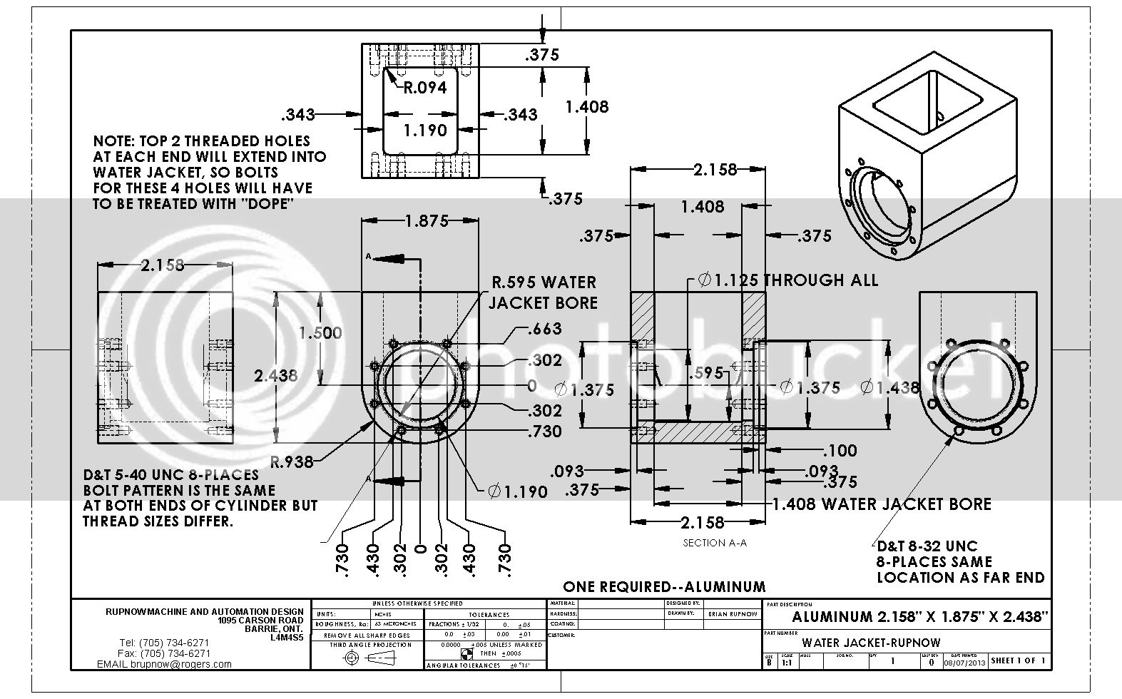
View attachment WATER JACKET-RUPNOW.PDF
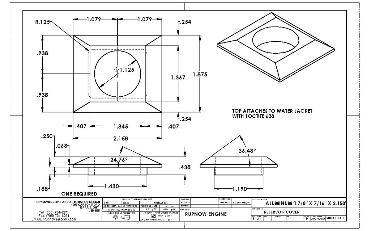
View attachment RESERVOIR COVER.PDF


View attachment CYLINDER-RUPNOW.PDF
View attachment WATER JACKET RETAINER-RUPNOW.PDF
View attachment WATER JACKET-RUPNOW.PDF
View attachment RESERVOIR COVER.PDF


")