Rockerblock I.C.--Something a little different-

Home Model Engine Machinist Forum

Help Support Home Model Engine Machinist Forum:

This site may earn a commission from merchant affiliate links, including eBay, Amazon, and others.
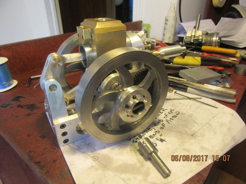
And now we have a combination drive-pulley and starter hub. The starter spud which I use in my variable speed drill is also new, laying in the foreground. That should be the end of the machining on this engine. The new points and condenser have been installed. All I need now is lots and lots and lots of luck. If I have lived a good clean life, etcetera, etcetera, the next post you see may be a video of the engine running.---Brian
 
Congratulations Brian
On a Fine Looking Engine, That made my Day,

DavidLloyd
 
Thank you David. The engine started up with very little fuss. At first I couldn't get it to fire, and was wondering what I could have done wrong. I checked for spark with a spark tester I made a few years ago, and it had lots of spark. Then I pulled the sparkplug and found a gob of oily goo setting on the end of the plug. After the plug was cleaned and blown off with compressed air, it started right up and ran.
 
Congratulations Brian, Another different runner. Running great for a first run, can't will wait to see how it runs on gas.

Cheers
Andrew
 
Nice one Brian.
Very compact and visually interesting.
Down the track I would like to build one.
Cheers
John
 
That is a really interesting motion to watch, and it looks to be another great runner. Nice work as always :thumbup:
 
Congratulations Brian!

This is a most interesting design. There are lots of interesting motions going on and it sounds great now. I look forward to hearing it after tuning.

--ShopShoe
 
Sometimes the engines I build run with no further work required on them. Sometimes I discover a "Gotcha". On this particular engine, it was designed so that at bottom dead center, the bottom of the piston skirt was flush with the end of the cylinder. After it's maiden run yesterday which I showed in the video, I seen something really strange. The skirt actually was protruding a good 1/4" beyond the end of the cylinder. This called for some head scratching. After deciding that there was no way the connecting rods could have "stretched", I looked more closely at the rocker support tower. The holes in the sideplates for the bolts which hold the rocker tower in place all have a standard "clearance" around the bolts. There is enough torque being transmitted to the rocker tower that it is tipping to the full extent of the clearance on these bolts. There are 3 vertically aligned bolts on each side. It is pivoting on the center bolt, and moving to the extreme left on the top bolt clearance and to the extreme right on the bottom bolt. After determining what was really going on, I set the rocker tower in the correct position and then drilled and dowelled the rocker tower and sideplates together with two 1/8" hardened dowels on each side. Then I went back and modified the drawings to show this alteration. The attached picture shows an "in process" shot of drilling and reaming the sideplates and rocker tower for dowels "in assembly".
 
Here are two more videos. In the first video, I try and speed the engine up and it quits. After it quit, I realized I was turning the throttle lever the wrong way, so there will be a second short video here in a few minutes. I will be selling a complete set of plans for this engine on a disc, as .pdf files which any computer can open, for $25 Canadian plus the cost of postage to wherever. If you are interested, email me at [email protected]
[ame]https://www.youtube.com/watch?v=evVJaytMsAA[/ame]
[ame]https://www.youtube.com/watch?v=19wanqj2ya8[/ame]
 
Now that I know the engine will run okay on liquid fuel, the next step will be to start "cooking with gas". I have a couple of valves and diaphragms from Jerry Howell, and the next part of this adventure will be seeing if I can get the engine to run on Propane.
 
Selling the plans for this engine is not a money making venture. I have designed, built and posted free plans for 13 or 14 of these small engines. Each small engine costs me between $100 and $300 to build for material, bearings, carburetors, waterjet cutting, etcetera. I know that people enjoy watching these builds, and I know that thousands of people have downloaded the free plans. (My hosting site has a counter and counts each download.) I build these engines for my own enjoyment, but it would be nice to recoup some of my own financial outlay. I have just gone through all of the drawings for this engine and updated them and saved them as .pdf files. There are over forty detail drawings, and at least two general assembly drawings in the package.
 
I'll be buying a set for sure Brian, just have to wait a little for some funds to free up. At this stage I have far too many projects already but it's a really unusual design so I must have it, plus I want to show a little support for the efforts you put in as well. I'll drop you an email soon hopefully.
 
That's great Cogsy. I always like it when you build my engines. They always look better than mine do by the time you are done with them.---Brian
 
Now comes the waiting time. In the "kit" I purchased from Jerry Howell to run this engine on propane, he mentions a specific regulator that should be used on it with a low pressure gauge. I found a Canadian rep for Coilhose Pneumatic in a city near here. I was able to order the regulator and valve, but it must be manufactured on Mars, because it is a three week delivery. At this stage of the game, I don't even know it this regulator screws onto a Propane bottle or how that connection is made. I am totally breaking new ground here, as I have never powered an engine on Propane. If anyone here has experience with this, please post a picture or give me a shout showing what you did.---Brian
 
I have chased down a number of semi-conflicting threads on this propane business, and it appears that if the regulator I have purchased will screw onto a Propane bottle, then all I need is the propane bottle with regulator attached, then a pressure gauge to monitor what pressure I am outputting, then a line to the "gas demand valve", then a line to the carburetor. However---Some of the threads I seen had a regulator on the propane bottle, which fed into the Coilhouse regulator, then the gauge, then the "gas demand valve". Some people have bought a regulator from Walmart which is used to run a Coleman stove on butane, some have used the gas demand valve, some have not. There is a lot of conflicting information out there, but as I make sense of it I will post what I did.
 
Hello Brian, LP gas is normally in liquid form. As it converts to gas, icing can occur at the most restricted area. If one uses the method for liquid to gas, such as auto use, the volume of liquid being converted to gas is quite high. In this case, a water heated regulator is used to stop the icing occurring where the reduction of pressure occurs. So the regulation of pressure occurs here. In small quantities such as your application, the volume of liquid being converted does not normally create an icing problem, so it is best to use a regulator at the bottle source, which allows low pressure tubes and connectors to convey the gas. Normal LP gas pressure is 11 inches of mercury, but I think one or two pounds pressure would be ample for your situation. I am in the slow process of running my engines on LP gas. I use hydraulic tube connectors and fairly solid plastic tubing for my connections. I think it is a good way to go. Best of luck, Norm
 

Latest posts

Back
Top