Rockerblock I.C.--Something a little different-

Home Model Engine Machinist Forum

Help Support Home Model Engine Machinist Forum:

This site may earn a commission from merchant affiliate links, including eBay, Amazon, and others.
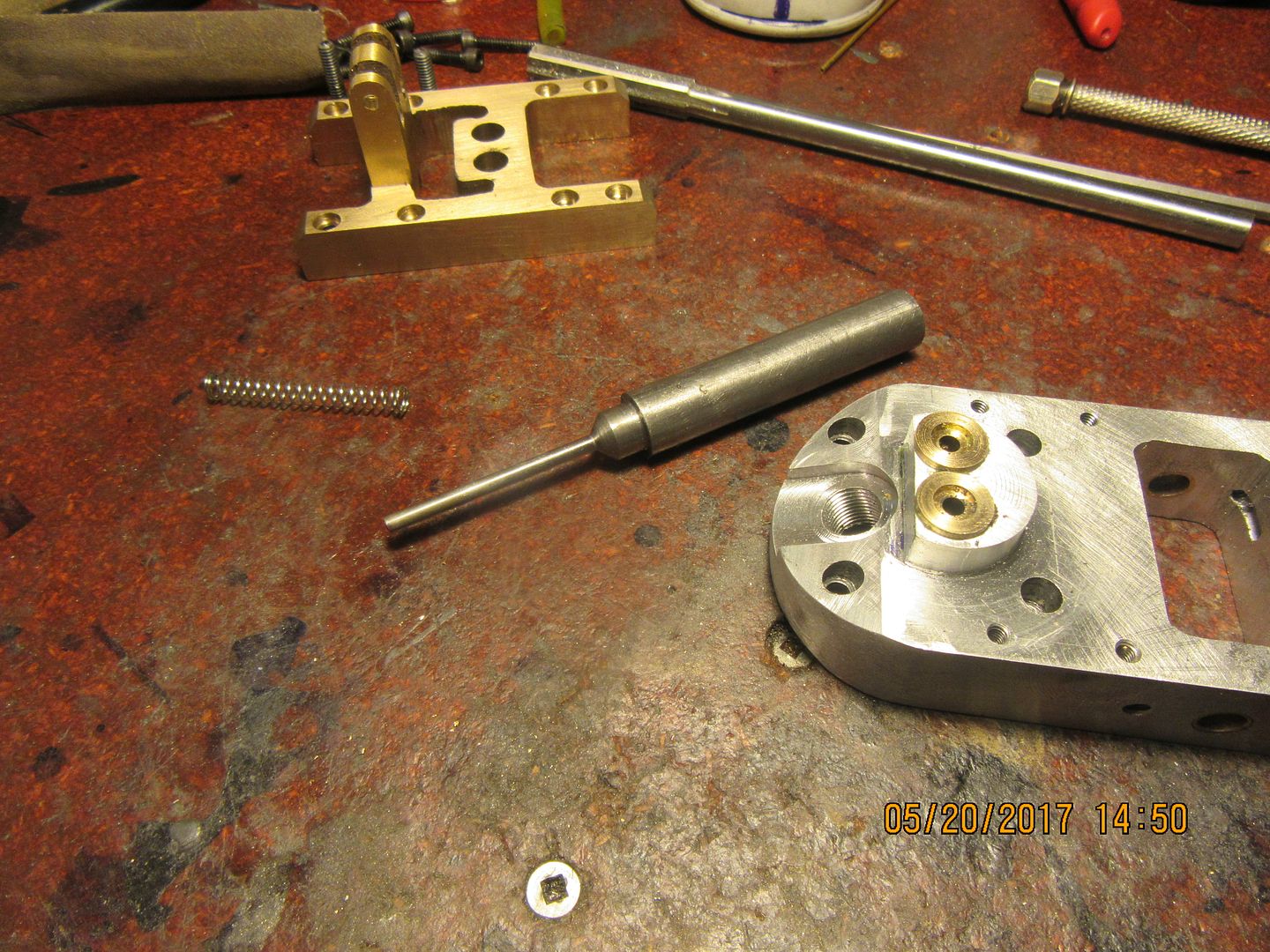
One valve down, and one to go. Both intake and exhaust are the same. The stem on these valves are almost ridiculously long, at 1.537", but once they are set into place in the cylinder head they look about right. The actual guided part of the valve in the valve cage is quite long. I turn these valves down to about 0.128" in 3 stages to keep from having a lot of deflection to deal with. The hardest part of the entire valve is to keep from turning the stem undersize. The last 0.003" or so, I work down to size (0.125") using 220 grit carborundum paper.
 
And that's the second valve finished. I'd have been done sooner, but I had to run across town to my sons house and look after a sump-pump emergency. Tomorrow I'll machine a set of "keepers" and drill that tiny 0.040" cross hole in the valve stems that allows a cross pin to hold the keepers and springs in place.
 
The time has almost arrived to make my rocker arms. I wasn't totally happy with the original design, as there was no good way to lock the adjusting bolt which sets the valve lash in place. So--this morning a couple of hours were spent redesigning the rockers. I'm happy with what I've came up with. I have to attend a birthday party for youngest grandson at noon, so I may not get any actual machining done today.----Maybe---
 
Those rocker arms look like monsters. They aren't really, they are only a bit less than 2" overall length. I will probably attach two 1/4" plates together and do the side profile, which is where most of the work is, then separate them and do the top profile, thinning them out to 3/16" in the center.
 
YOWZAHHH---we got rocker arms!!! I had forgotten that today was a holiday. I got ready to travel to my office across town this morning and good wife said "where are you going? It's a holiday today."---So, today I machined the rocker arms I redesigned yesterday. There is a lot of work in those rascals. I spent most of today making them.
 
Made a mistake--Kissed a snake--ah, POOP!!! I totally screwed up the design of those rocker arms. I can't even see a decent way to modify the existing ones and "save" them. As for some idea of what I did wrong, look at the drawing I posted. The actual part of the rocker arm or the adjusting screw that contacts the end of the valve stem should be almost dead-nuts in line vertically with the pivot hole in the rocker arm. Pulling it away off center like I show in the 3d cad model means that instead of an almost vertical up and down movement, which is what you want to have acting on the valve stem, it "swipes" across the end of the valve stem as it pushes it down. This produces undue wear on the end of the valve stem and also tries to make the stem bend sideways as the rocker rocks up and down. I will have to make new rocker arms, and probably have to make an adjustment to the height of the rocker pivot tower. Fortunately this hasn't cost me any money.--Just the best part of a days work. One more thing to file away in my mind about what you can and can not do when designing these little engines.---Brian
 
To give you some idea of what I'm talking about, the dotted line indicates the optimum position for the rocker arm pivot, in relationship to the end of the valve stem. Arranging it this way gives the absolute minimum of "side movement" on the end of the valve stem when the rocker arm rocks.
 
So---I'm back to where I was a week ago. The new rocker arms are made, and although they look an awful lot like the old rocker arms, there is a big difference in the geometry of the area where the adjuster screw sets. I shortened up the height of the rocker arm support tower by about 1/4", as that played into the overall geometry as well. Now I have to quit playing machinist and go help goodwife get ready for a yard sale tomorrow.
 
Here's a little trick I have found. The adjusting bolt in the end of my rocker arms is a #5-40 thread, but a #5-40 hex nut is huge when it's up against something 1/4" wide, like my rocker arms. The trick is to get a #4-40 hex nut which has a considerably smaller outer profile, and drill/tap it out for a #5-40 thread. It looks much better, proportion wise.
 
Hi Brian, watching this thread with interest as do all your threads
Drilling and tapping a larger size in a hex. nut is common practice
when making model steam locos,although small hex nuts can be
purchased with the hex a size smaller than the thread purely for
looks.Good thinking
 
No machining to report today. Goodwife has been collecting donations for about 6 weeks to have a "Parkinsons Charity Yardsale" in support of the Parkinsons foundation. Our 41 year old son developed Parkinsons Disease a year ago. My garage was stacked right to the ceiling with other peoples junk, so yesterday involved setting it out along both sides of my 100 foot driveway and doing the yardsale thing. After a furious two hours of setting everything out, with help from our son and two of his children, I spent most of the day setting in a big old (donated) chair and helping wife oversee the yard sale. The sale went very well. We made over $600 for the charity. About noon my son and his two young children were getting pretty worn out, so we sent them home. We had a couple of small passing rain showers, but not enough to wreck anything. At the end of the day, even though we had sold a ton of stuff, there were still 2 tons of "stuff" left in the driveway, which Kathy and I had to then pick up and cram back into my garage. The next 2 weeks will see her donating everything that was left to various organizations around Barrie. It was a fun day, and the first day in months that I haven't been designing for a customer or working in my own machine shop on the Rockerblock engine. I'm sore today from using a lot of muscles that don't get used very often. ----Brian
 
It's kind of hard to believe, but I only have 6 parts left to make on this engine. I need two cams, two lifters, and two pushrods. Since I am used to operating these small engines on Naptha and oil mix, I will probably set it up to run on Naptha and oil initially. Once I get it to run with a fuel I am familiar with, then I will build the gas-demand valve and see if I can get it to run on propane. I thought I might have things completed by the end of May, but life gets in your way sometimes, so now it will probably spill over into June. I have "bits and bobs" of minor tweaking to do, but other than the 6 components mentioned, all the major parts are finished. I will use the same method for making the cams as I did for the Rupnow Vertical engine and the Overhead cam engine, using the rotary table and milling machine. That method isn't as accurate as the method outlined by Malcolm Stride, but it doesn't seem to matter that much. The engines run well no matter which method is used.----Brian
 
Tonight we have finished valves. After the killer yard sale on the weekend, and working "away" today, I hadn't planned on doing anything tonight.--But you know how it is---Just had to do some little thing to keep the flame burning. My valves always look a little "ratty" on the ends after the parting off operation, but I don't try too hard to clean them up perfect. I grind away any "tit" left on the center on my belt sander, but I don't try to polish out all the concentric circles. The heads of the valves don't show after the engine is assembled, and I did actually ruin a perfectly good valve once, getting too enthusiastic about taking out any marks left after the parting off operation.

 
This morning I cut the first cam. It turned out well although I find that every time I cut a cam using the "end mill plunge" system, the results are always marginally different from the input math I used to set it up. The engine won't mind, as long as both cams are identical. I still have to file a slight radius on both sides of the tip. I won't change any settings when I put my next cam blank in to machine it. That should guarantee that both cams are the same.
 
I've just read the entire thread. Being a complete noob to model engine building I'm amazed at the talent. I've worked as a machinist, since high school, repairing & fixing but, didn't know what I didn't know until getting interested in model building! Can't wait to see the finished project.

Jack
 
Here we have two little cam birds setting in their nest. They are not hardened yet. I have just finished turning the lifters, and am working on the link between the lifters and the rear side of the rocker arms. Both cams and lifters are made from 01 drill rod, which I will flame harden. If all goes well and I have no disasters, I will finish the valve train on Friday.
 
We have an operational valve train!!! The cams go round, the lifters lift, the rockers rock, and the valves open and close. I still have a bit of fettling and fondling to do, but it works. I haven't cut my valve springs to length yet, as everything has to be disassembled, the cams and lifters hardened, and intake/exhaust ports drilled into the cylinder head. I was supposed to work (real work) today, but at the last minute it got deferred to tomorrow, so I had all day to play in my machine shop. I'm quite excited about this as the valve train is the last major sub assembly on the engine. The solid model shows what I did for a pushrod.

 
And a beautiful thing it is!! After a days work "away" I came home tonight and after some very careful set-up, drilled, tapped, and spot-faced the cylinder head for the intake and exhaust elbow fittings. The holes ended up where they were supposed to be, and the elbows fit the way I had hoped.
 

Latest posts

Back
Top