Plunket Jr. Build

Home Model Engine Machinist Forum

Help Support Home Model Engine Machinist Forum:

This site may earn a commission from merchant affiliate links, including eBay, Amazon, and others.
Thanks Jeroen and Bill :bow: :bow:

Jeoen, regarding the stepper motor. That sounds pretty good, but I'm not ready to go in that direction at the moment. There is a reasonable chance I will be moving in the next year or so. Once I settle somewhere I think I might go the whole hog with a CNC mill and rotary table etc. I also know someone here who has vast experience with Mach3 and CNC conversions. Thanks for the offer. When I finally get round to going CNC I will be sure to be in touch with you.

Regarding the bevel gears. I have never done it. However I have some excellent literature on the subject in the form of an ancient book by Brown and Sharp. If you want I can scan the relevant section and send it to you. I think the copyright has expired on the book.

Cheers
Steve


Hi Steve,

Thanks for the offer, I would like to receive some detailed material on bevel gears! I have send you an personal mail with my mail address.
Thanks in advance for the taking the effort to scan and send me the material, it appreciated.

Best regards Jeroen
 
Steve,

great work on the gears, gears always impress me but those have turned out spot on. I don't think I'll ever be able to make them!

With regards to the QCTP - it might get on my project list :big: but I have 3 projects to finish first, 2 off poppin flame lickers, electric loco and tiny stirling - all at various stages of unfinishedness!!!

Nick
 
I really admire your courage Steve, machining the timing gear directly onto the crankshaft! no room for error there..great work!
 
Thanks Nick and Compspecial

Nick - of course you can make gears. Just get your hands on some cutters and go for it ;)
By the way I like the project list, could be a little larger though :p

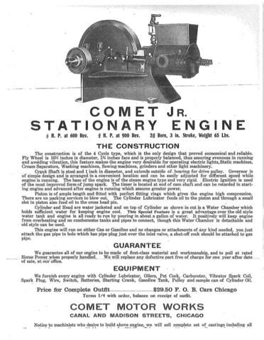
I did some snooping around on the net and found some stuff about the original Plunket Jr. First a flyer for a brand engineered version. Interestingly it says that it was also available as a casting kit

comet.jpg


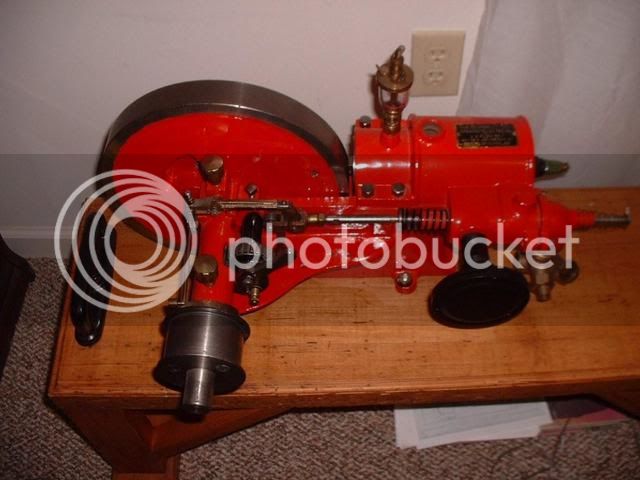
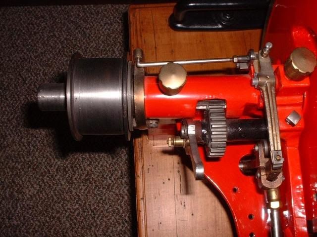
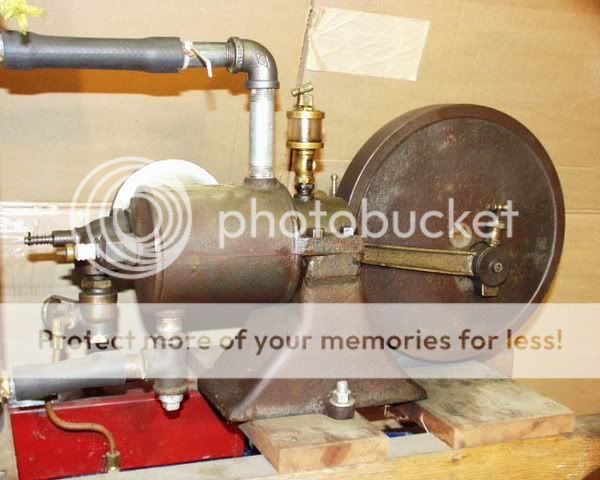
and some pics of originals, which have been posted up somewhere by their owners. Apparently it was sold in various configurations, some with throttle control, some with governors, and some with water hoppers

DSCF0001.jpg


DSCF0013.jpg


PLUNK1.jpg


Cheers
Steve
 
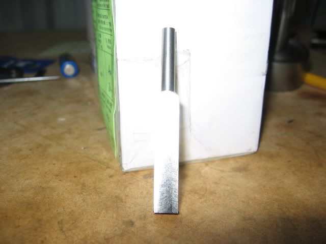
So I went a bit nutty and made a miniature cricket bat out of stainless steel

IMG_0779.jpg


Only joking, it's going to be a sort of push-rod for the exhaust valve.

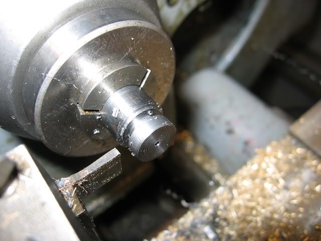
I made a wheel to go in the end out of a bit of 1/2" silver steel. It has a 1/16th hole through the middle. I'll harden it later

IMG_0778.jpg


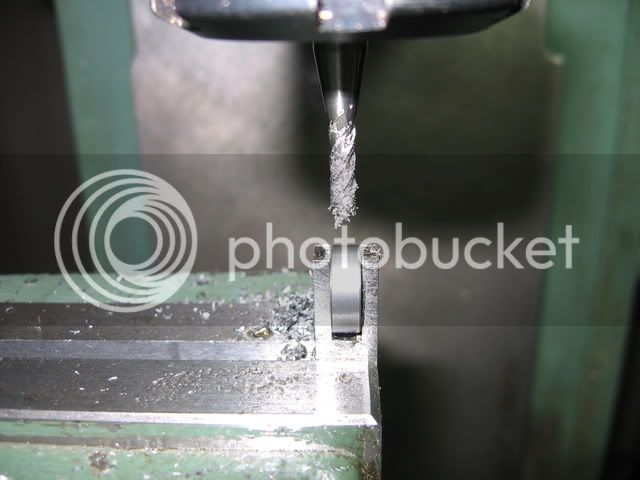
and then did various more milling operations on the cricket bat. You can see how the roller fits in the end here

IMG_0780.jpg

 
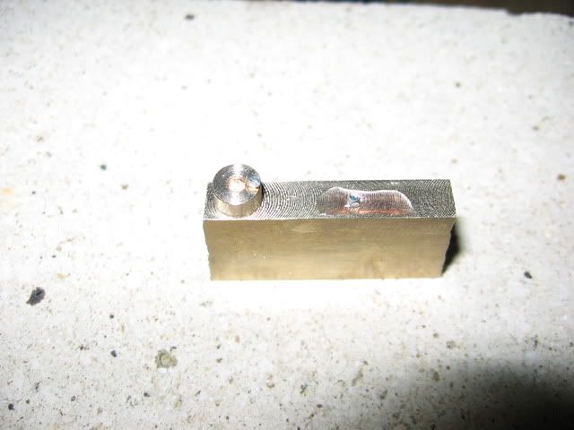
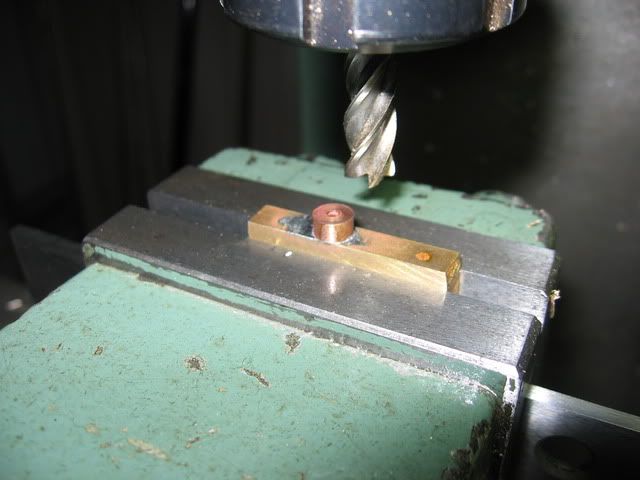
I didn't photograph this bit, but the cricket bat now has a slot in the middle to slide back and forth along. Next I needed a bronze guide which goes inside this slot. The bit was really small and difficult to hold, so I soldered it onto a bit of brass

IMG_0781.jpg


and then milled it to fit in the slot in the cricket bat

IMG_0782.jpg


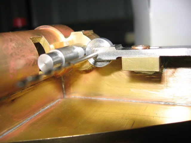
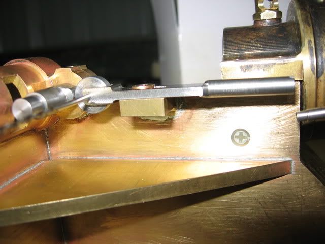
Here's a couple of pics of a mockup of how the whole thing goes together. I'm using a 1/16 drill to hold the wheel as I haven't made the proper axle yet.

IMG_0783.jpg


IMG_0784.jpg


You can see how the wheel runs on the cam, and how the other end pushes the back of the exhaust valve. In the middle you can see the top of the bronze guide. This will have a screw holding it onto the little shelf that the cricket bat is sitting on.

Steve
 
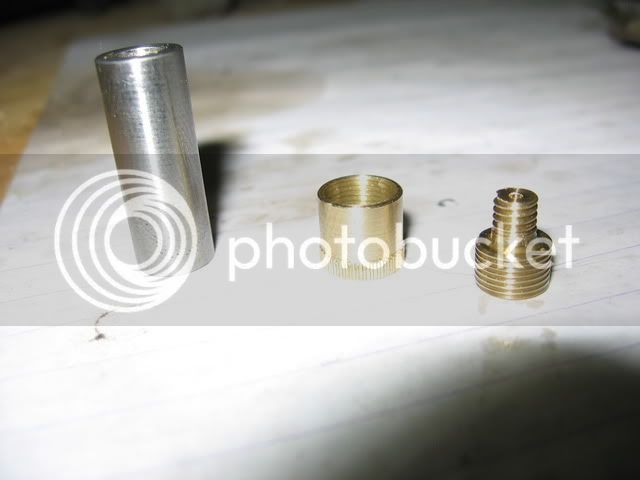
I made the grease cup to go on the crank pin. I purchased a fine straight knurling wheel for the job

IMG_0776.jpg


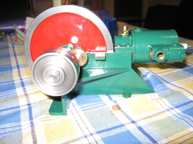
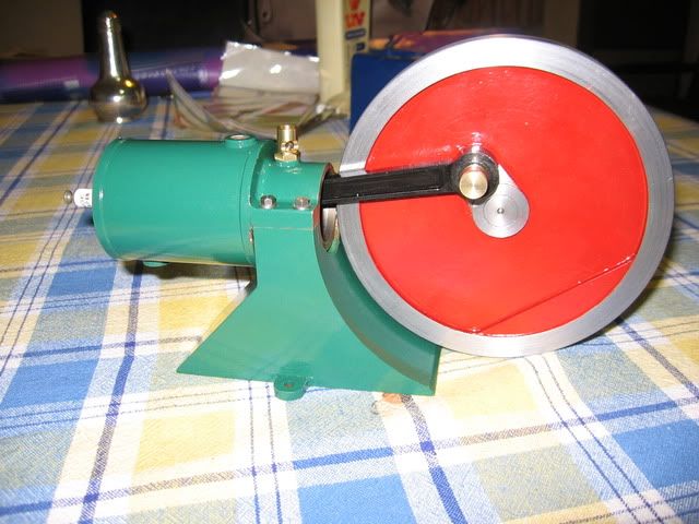
and then did some painting and assembling

IMG_0786.jpg


IMG_0785.jpg


The green is a fair bit darker than it appears to be in the picture on my computer. I'm not planning to do anymore until the new year

Cheers
Steve
 
I haven't had a chance to catch up on the forum for a while but that is looking great Steve. Best colours for an engine in my opinion - all my flywheels are red, although somebody did do one with a cream flywheel recently which also looked really good!

Nick
 
Thanks Nick,

I also like red for flywheels. I haven't seen a cream one yet, I'll have to keep my eyes open.

Hopefully I'll get a chance to do some more on this in a few days. The main things I have still to do is, get the valves and associated parts finished and working, make the carby, make a water pump and make the radiator. Then hopefully get it to run.

Cheers
Steve
 
Thanks Nick, the cream flywheel does look good

I've got some more work done on my engine. First the paint didn't work out any good, as the primer I used was wrong. I've got some etch primer now, seems to have worked good.

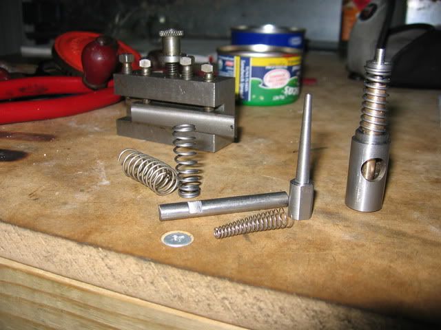
I've been experimenting and made the valve springs. Here's a pic of the spring on the exhaust valve assembly, some of the earlier attempts I wasn't happy with, the inlet valve spring which is the small tapered one, and the mandrels I made to wind the springs on

IMG_0789.jpg


The flats on the mandrels have the spring wire pinched between them and one of the jaws of the self centering chuck. Also shown is the guide for the spring wire that is used to wind the spring, in the lathe using the screw cutting mechanism. The tapered spring will fit over the tapered end of the valve guide for the inlet valve.

Steve
 
It's always nice to see your progress Steve! The springs look great as does the engine.

Bill
 
Thanks Bill, nice of you to say that

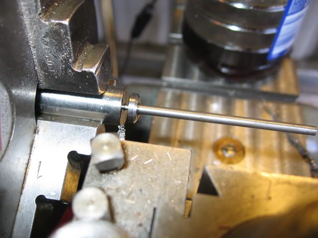
I did some more work on the inlet valve assembly. Here's the valve stem just before being parted off. It's some sort of stainless, parts off ok with good cutting oil, hopeless without it. The stem came out nice and parallel with tailstock support.

IMG_0790.jpg


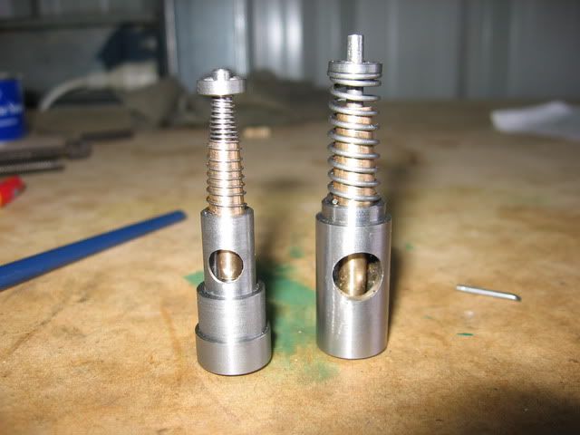
Here's the finished inlet assembly on the left and exhaust on the right. The inlet is opened by vacuum, hence the weaker spring

IMG_0791.jpg


Steve
 
Steve, those turned out very very nice!!!!! Great pictures too as always.

Bill
 
Springs did turn out great Steve, out of interest did you temper them?

How strong is the inlet spring? In the pic it still looks quite springy but it is a bigish engine and difficult to get an idea of size.

Nick
 
Steve, I've been quietly lurking along...
You're doing a great job on your build :bow: :bow:

Silly question - the tapered spring looks great, but won't it want to start to catch on the taper of the valve guide in operation, as it looks to be a fairly close fit to the "cone" ?

Kind regards, Arnold
 
Steve, its looking great! It will be such a beauty when finished.
Did you polish the valve stems or did they came out of the lathe that smooth. I can hardly see some machining traces....

Regards Jeroen
 
Thanks Bill, Nick, Arnold and Jeroen

Nick, I just made the big spring out of piano wire that I bought at the local hobby shop (RC planes etc.) and the smaller one out of stainless spring wire. I was going to make them both from stainless but I didn't buy as much as I should of. No tempering, just wound them and be dammed :p In my limited experience that works good. The exhaust spring is pretty strong (39 thou piano wire) but I can still move the valve between thumb and finger with just a little effort. The inlet spring is considerably weaker (16 thou) and very easy to squash between fingers.

Arnold, sounds like a good question to me ;) The tapered spring fits tight on the cone. Only the part in front of the cone moves when the valve is compressed. The original Plunket seems to of had this type of arrangement.

Jeroen, I didn't polish the valve stems. The stainless I used is not free cutting but still machines good for stainless, hasn't given me any trouble with work hardening. It gets a nice smooth finish with an ordinary off hand ground hss tool very easily. Relative to mild steel the harder steels are often easy to get a smooth finish on with hss. I'll do a little lapping for the seat, I made the taper face about half a degree miss match so it contacts on the large end of the seat.

Cheers
Steve


Thanks Steve, sounds good to me. Is there any way you can test those valves for leaks as is or will you just wait until they are assembled into the head and with the rest of the engine?

I got some carbide tipped tools last christmas but couldn't get anywhere near the same finishes I can with a hand ground HSS bit so I was quickly back to those. Probably something I'm doing wrong with regards to cutting speeds or something but I just do what I know works now. My lathe only has a max speed of 720rpm but I have hardly ever needed to use it with the HSS tools.

Nick
 
Back
Top