Plunket Jr. Build

Home Model Engine Machinist Forum

Help Support Home Model Engine Machinist Forum:

This site may earn a commission from merchant affiliate links, including eBay, Amazon, and others.

swilliams

Well-Known Member
Joined
Mar 28, 2010
Messages
239
Reaction score
0
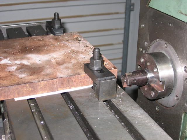
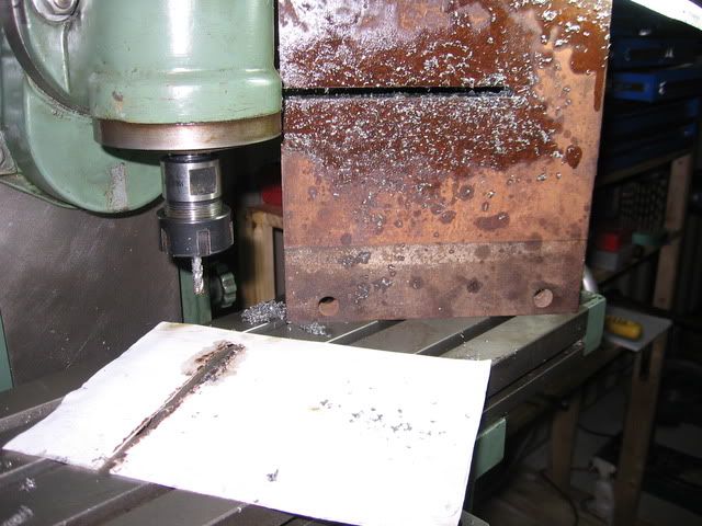
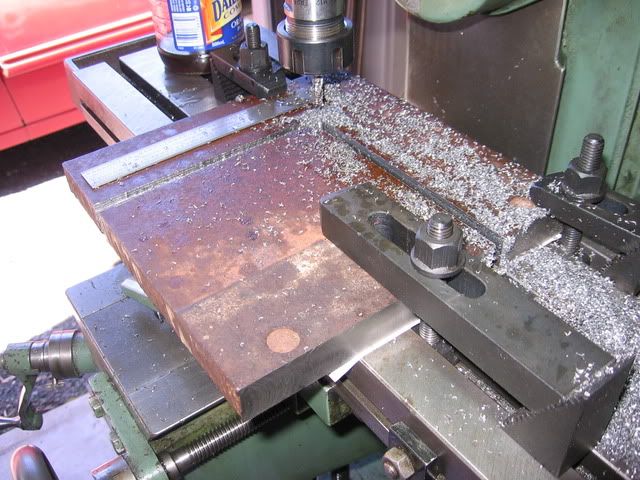
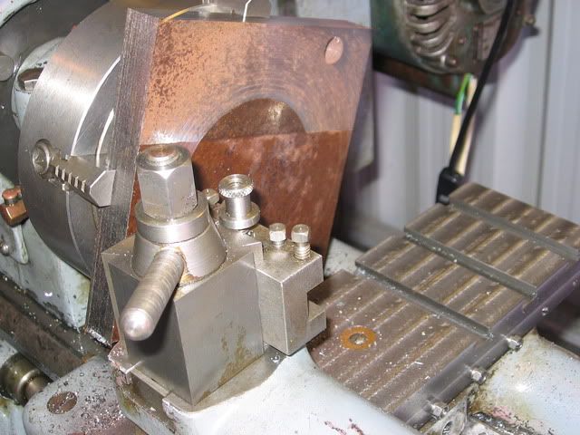
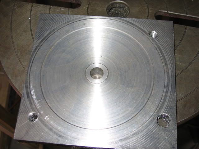
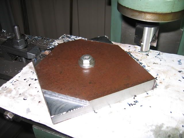
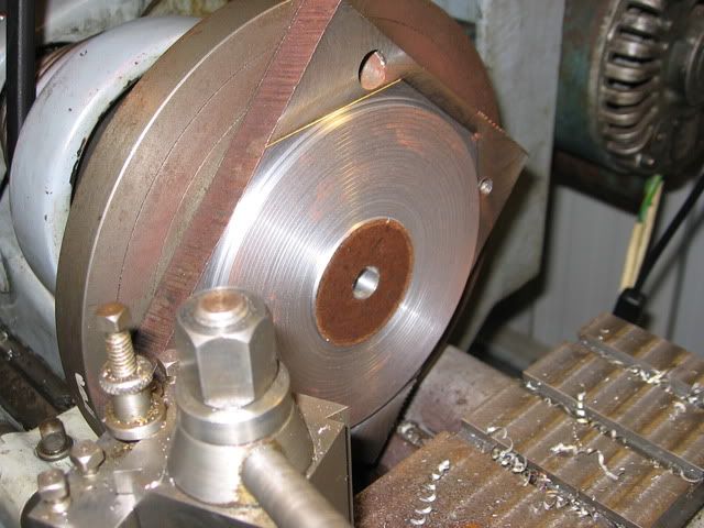
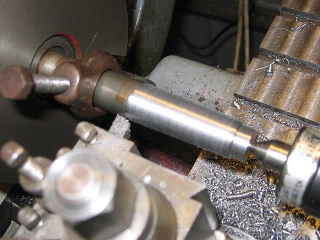
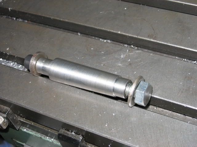
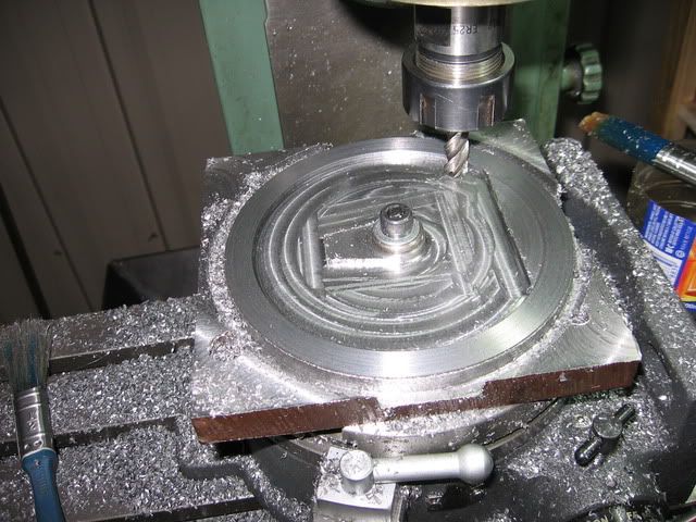
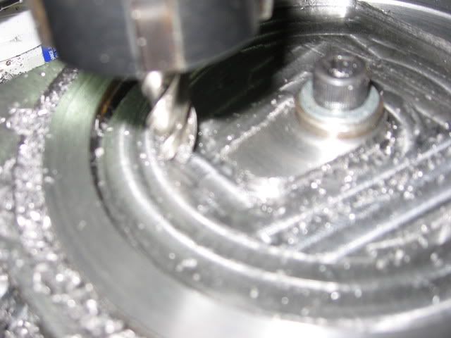
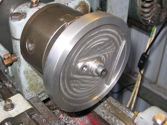
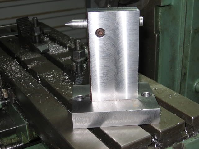
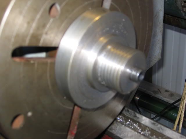
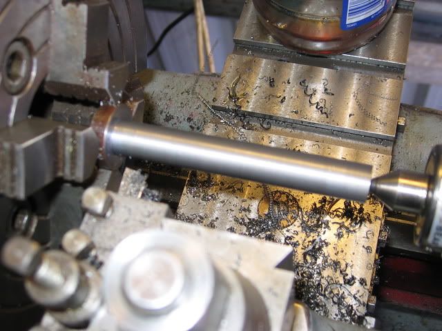
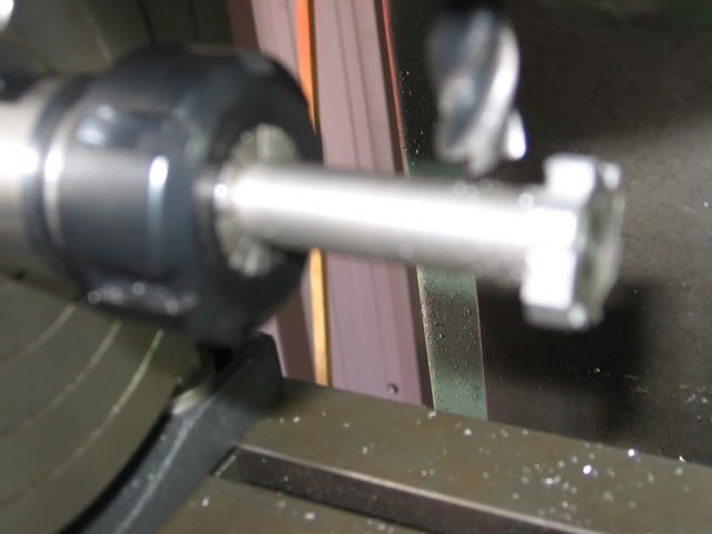
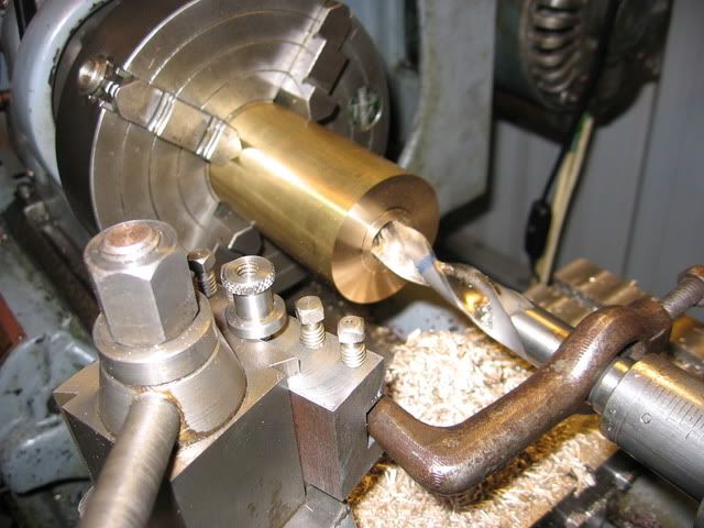
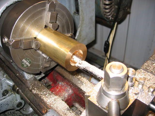
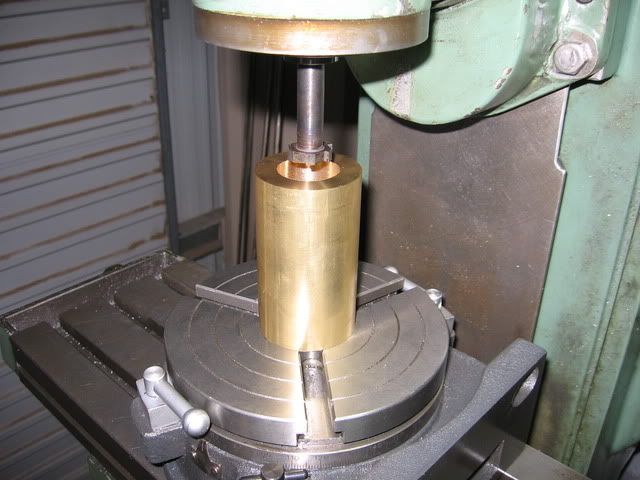
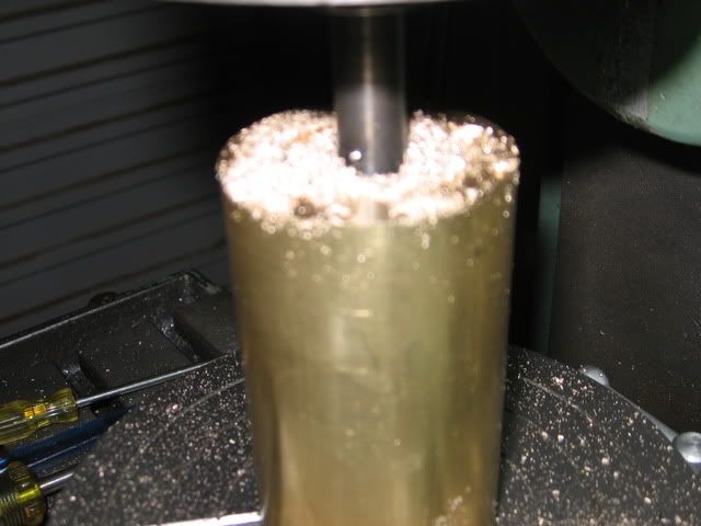
This is my first attempt at an IC engine, very close to my first engine, although I'm not new to machining. The model is to Jerry Howell's design, and made from bar stock.

http://www.model-engine-plans.com/engineplans/combustion/plunket.htm?33,12

According to the plans the original engines were made about 100 years ago to power domestic machines such as washing and sewing machines. They weren't a very successful product and now are very rare and collectible.

Hopefully someone around here can point me in the right direction if and when I get over my head

Regards
Steve
 
I decided to start with the flywheel. The engine has the crank pin straight in the flywheel for the big end to connect to and some balance weights. So the flywheel has a couple of non round features requiring quite a bit of milling on the rotary table.

I started with a bit of steel plate. First I milled a reference surface which will be used later

IMG_0566.jpg


The plate was too big so I cut a smaller square out using a roughing endmill. I didn't have anything better to do it with and it worked ok

IMG_0567.jpg


Apparently an endmill is pretty good at cutting paper!

IMG_0568.jpg
 
I then started turning the flywheel. This photo was taken with the lathe running, the cut was not just rubbing like it looks. I was using a carbide tool with the slowest direct drive speed.

IMG_0569.jpg


After the wheel looked something like this

IMG_0577.jpg


I got ready to do the other side. I needed to take about an 1/8" off the back side, so I milled the corners off to avoid the massive interrupted cut on my little lathe

IMG_0571.jpg


Then I stuck it on the face plate and made it the same as the other side.

IMG_0572.jpg


From here it's mostly milling.
 
Looks like you are off to a good start Steve. That's gonna make a fine looking model judging by Jerry's pictures.

Regards,
Bill
 
Thanks Bill, still very early days, hopefully I can do it justice.

My rotary table has a second Morse taper in it. I decided to make up an MT arbor to mount the flywheel on the rotary table.

I turned the arbor between centres using the topslide for the taper. I set the topslide by clocking up against a 2nd MT centre held between centres in the lathe.

IMG_0573.jpg


The arbor has a thread in each end so I can first bolt it into the rotary table and then put a bolt in the other end to hold the flywheel onto the rotary table

IMG_0580.jpg
 
I rounded the corners off an old 10mm endmill free hand on the grinder and used this to mill the flywheel.

IMG_0575.jpg


IMG_0576.jpg


I used the roughing endmill again to start trepanning the wheel out. I only went half way through as I wanted to preserve the reference surface. This was used to make the counter weights on both sides line up.

The flywheel was then turned over and the other side done. The wheel was cut out and put back on the lathe for finishing off

IMG_0579.jpg


That's it for now. Hopefully I can make some more progress before too long

Regards, Steve
 
Nice looking build, Steve. Looks like you're creating quite a pile of chips!

Chuck
 
Thanks Chuck. You are right, I've sure made a big mess (of chips)

I guess I should do some cleaning up :-\
 
Wow, bet that took a while to whittle away! Nice work :bow:
Nick
 
Hi,

Well you haven't gotten to the point where you need a shovel yet ;D and I like seeing lathes with chips on then.

Looks great!

Dave
 
Thanks Nick and Dave

Nick - yes it wasn't the speediest of operations. Trepanning with the endmill took a bit of time

Enough chips to require a shovel hey Dave? Perhaps I need a bigger lathe ;D
 
HI and you is playing nice a grate billd regards bob
 
Thanks Bob and Pat

Pat, I hadn't given cast iron much thought but it sounds like the way to go. I used that steel because I already had it. It was slow but not unbearably so.
 
I've been making a few tools I need for further progress. First a tailstock for my rotary table. The upright piece was made from what was left over in cutting the flywheel out

IMG_0592.jpg


Second an adapter to put my lathe chucks onto the rotary table, here it is nearly finished

IMG_0565.jpg


and finally a special cutter for the cylinder water jacket. This is made from an old piece of rusty silver steel (drill rod)

IMG_0581.jpg


IMG_0586.jpg
 
The plunket is an interesting engine. I will enjoy watching you build this. One question, how do you plan to cut the small valve gear in the crankshaft? Will it take a special cutter?

Chuck
 
Thanks for the interest Chuck, it's appreciated. Have you built a Plunket or are you planning on building one one day?

I'm planning to make a cutter for the gear. I've all but finished a Eureka tool and this will be a good thing to test it out on. As you probably know the Eureka is a tool you put between centres to make a form relieved gear cutter. It works with ratchets and eccentrics such that one of the cutters teeth go by for every revolution of the lathe spindle. I am very curious about getting this device up and going. I bought some tool steel to make the cutters from.

If all else fails I'll just buy some cutters. 0.8 module is close enough to the DP specified in the plans and I can get the two cutters for 30 bucks including postage from CTC tools, http://www.ctctools.biz

Cheers
Steve
 
I get a bug every now and then to build one, but haven't gotten real serious about it. I'm more interested in some of the techniques used on the engine. What's the diameter of the crank where the gear is cut? Also, how many teeth?

I've seen the Plunket running a number of model engine shows. It sure does run and sound nice.

By the way, I have seen the Eureka tool. Looks complicated...

Thx...
Chuck
 
The diameter is 1/2", 14 teeth and 32DP. The other gear it meshes with is 28 teeth
0.8 module corresponds to 31.75 DP

There are also two very small gears for the water pump (gear type pump). 10 teeth only, I will probably increase the pressure angle for these beyond 20deg.

The Eureka wasn't so hard to build, but I haven't got it running yet so perhaps I should shut up on that score :-[

regards, Steve
 
I made a start on the cylinder housing. The cylinder is water cooled and consists of a brass housing with a cast iron linear. There is one port at the top of the cylinder that both the inlet and exhaust go through. This port goes through the water jacket and so some milling has to be done to accommodate this.

Started by boring the water jacket out, was a little worried about the drill jamming up but it turned out fine

IMG_0594.jpg


then boring

IMG_0595.jpg


So now I have a hole that is slightly less than the cylinder linear outside diameter.
 
Next to the milling machine to open up the water jacket. I drilled and tapped a hole in the back of the housing to mount it to the rotary table. Then I used the special cutter I made earlier.

IMG_0596.jpg


which soon resulted in a sea of chips

IMG_0597.jpg


So if you look at this next photo carefully you can see there is a small piece near the front that still has the smaller diameter of the cylinder linear. This will have a hole drilled through it from the side and also through the linear to create the port.

IMG_0603.jpg
 
Back
Top