Plunket Jr. Build

Home Model Engine Machinist Forum

Help Support Home Model Engine Machinist Forum:

This site may earn a commission from merchant affiliate links, including eBay, Amazon, and others.
Really starting to look like an engine now, Steve.
All that brass makes my heart go pitter-pat. There is
absolutely nothing in the world that can't be improved by the addition
of some brass Thm:

Cheers, Joe
 
Yep, well done Steve, great work. I've always liked the look of plunket but had no idea how complex it was! No wonder it says not for beginners on the website.

Nick
 
Bill, Joe and Nick, thanks for checking in and the nice words :bow: :bow: :bow:

Bill, I'm planning on painting it, I've gotta cover up those ugly screws holding the base together :eek:

Joe, I'm liking brass more and more as this build progresses. The way cheap crappy endmills keep on keeping on is a real plus.

Nick, Yes it's more complex than I expected to. However from where I sit now (reckoning I've got the hardest work behind me) that makes things more interesting. Famous last words :p
 
Steve,

Great work :bow: :bow: I really like the way you have fabricated complex shapes and blended them together.

Best Regards
Bob
 
Thanks Bob :bow::bow: It was a little bit of a struggle, glad that parts finished
 
Hi Steve,

Pass by to put here my compliments on your build, really well done and very educational to make complex shapes build up out of standard material :bow: :bow:

Best regards Jeroen
 
Thanks Jeroen. Still lots more to go

Next is the power take off pulley

Here's the bit of steel I made it from, this used to be 50mm ground bar about 25 years ago. Now it's got a more natural finish

IMG_0752.jpg


I ground up a form tool for the job out of HSS

IMG_0753.jpg


and made a start on the lathe

IMG_0754.jpg
 
Next was cutting the keyway. Last time I tried this I was unhappy about the way it punished my puny lathe. This caused me to build a slotting attachment that I finally finished off for this job and put into service

IMG_0755.jpg


IMG_0756.jpg


Then I finished the outside, by mounting it on what will be the crankshaft and driven by the key. The crankshaft is made from 1/2" silver steel. I decided to go all old school and put it between centres

IMG_0760.jpg


I put the crown on with the topslide and file.

Here's the finished product. All that's left is to put a hole in for the grub screw which locks it on.

IMG_0769.jpg


I could do a bit more work on the polish, but I'm not a big fan of polishing.
 
Wish my soldering was up to your standard steve :bow: did you free hand grind the form tool ? looks like you got a smooth radius.
yours
peter
 
I think your fabrication job is really great Peter, I'm very impressed :bow:

Yep, ground the tool freehand. It wasn't perfect but turned out near enough

 
Steve,

brilliant work.

Like the slotting attachment. It is a classier way to attach wheels to a shaft with a key way, looks far superier to any other method in my opinion!

Nick
 
Thanks Nick

I got enthused and built that attachment shortly after upgrading my milling machine about a year ago. Before that I had an old piece of junk horizontal without a vertical head. I was enthused about cutting some dovetails at the time. Of course there's easier ways to go about it. I've seen some nice pictures from members here who put a lever attachment onto the back of the topside.

If you have a big strong lathe, just winding the carriage back and forth works great.
 
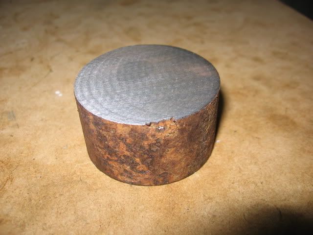
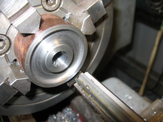
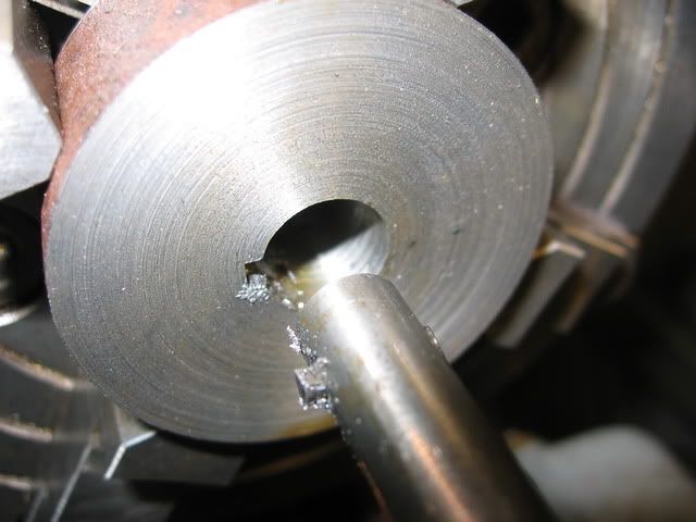
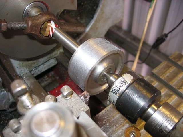
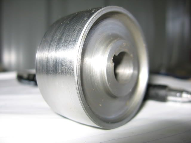
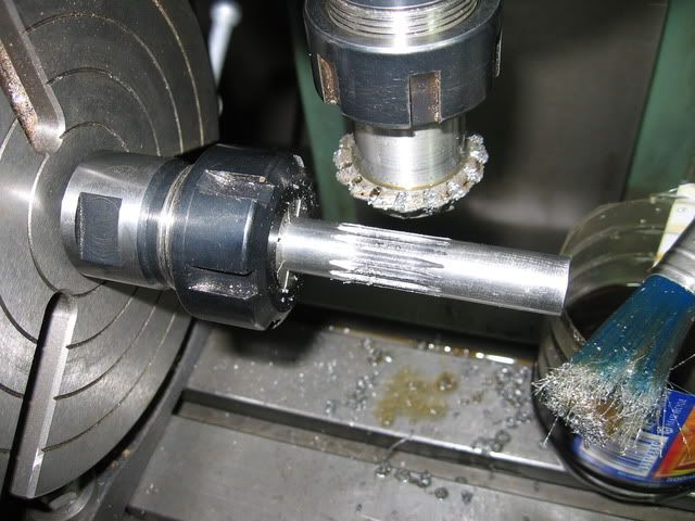
I've got a harrison L5 and to fit the new motor I had to put a key way into it so I did that by winding the carriage back and forth, it worked really well but was only an aluminuum pulley. Even then it felt like I was punishing the lathe a bit though!

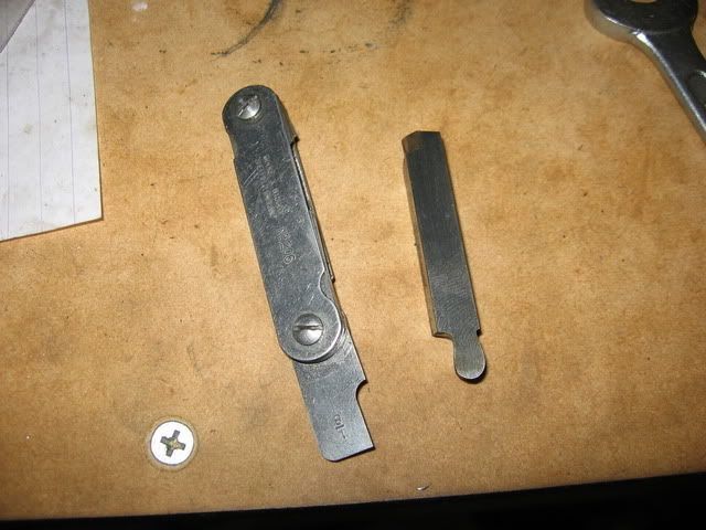
I always fancy cutting dovetails too! I've got a cutter that was given to me but never tried it, one day I will make a Quick change Tool Post, one day!

I know what you mean about the horizontal, I had a lovely centec 2a until a few months ago, I'd used it about 2 or 3 times then bought a larger vertical so it was never going to get used again. It was a good quality machine though, someone got a bargain.

Nick
 
Building a quick change toolpost is the way to go Nick. Once you do it you'll be kicking yourself for not building one years ago. Make a dozen or more holders, takes all the tedium out of turning.

Steve
 
I do find it really tedious changing tools, finding tools, setting centre height etc. especially as my tool post only accommodates 1 tool at a time! I have planned to make the tool post and holders for a while, but then I think, I could be spending that time making engines. But I guess it could be rewarding too, because then I'll be using it all of the time.

I'm too tight / can never afford to buy one!

Thanks,

Nick
 
Hi Steve,

Nice work on the tool indeed, whenever I try this I end up with a radius of 0.1mm. I do not know when to stop and probably I do not have the skills for free hand radius shaping :D

Nick, there is no greater joy then to use your home made tools. It's not just a matter of money, but I appreciate a lot more my own made tools then the ones I bought.

Keep the pics coming, regards Jeroen
 
Thanks Jereon. Yes I agree about enjoying building tools that you use. So Nick have we badgered you into building that QCTP yet, or do we have to get more sanctimonious? :big:

Anyway back to business

I made the cam

IMG_0751.jpg


Also I got some gear cutters from CTC tools. They are 0.8 module which works out at 31.75 DP instead of the specified 32 DP. I decided the prices were such that I couldn't justify messing about to make my own,

http://www.ctctools.biz/servlet/the-Cutting-Tools-cln-HSS-Involute-Gear-Cutters-cln-Individual-Gear-Cutters/Categories

I'll still have to make my own cutter for the gears in the water pump later
 
So then I cut the timing pinion in the crankshaft

IMG_0767.jpg


and made up the timing gear (more super glue for holding in the lathe)

IMG_0770.jpg


So here's how this bit goes together, the timing gear goes over the cam and is attached with loctite.

IMG_0774.jpg


The cam and the pin it rotates on are made of silver steel. I'm planning to harden and temper them later. I also need to attach the little magnet to the brass gear for the Hall effect ignition.

The main thing I learned from this part of the build is that I need to buy some dividing plates for my rotary table ASAP :p

Regards
Steve
 
Hi Steve,

Nice job on the gears! I find gear cutting one of the most satisfying jobs to do, it has something magical to me. If I may give you an advice, truly concider to mount a stepper motor on your rotary table instead of working with plates. You can control it with Mach3 or a dedicated angle control unit. I found that working with plates and the shear lead to mistakes. What goes wrong with me is that when rotating to the next position you need to pull the handle to unlock the table. Many times I hit the shear when rotating and then your reference is gone! The worst thing is that you only know if you repositioned correctly when you cut the last tooth :( Sine I made my rotary table stepper controlled I had no positioning problems anymore. If you want I can post some pics of what I made.

Another thing. For my Stanley steamer I need to cut 2 gears in a 60 degree angle. I would like to use the standard gear cutting disks like you used. I cannot figure out how to do it, because the blanks are conical so it's hard to determine the blank diameter that I should use for calculations. Also I cannot find any article or info about cutting gears on a angle. Do you have any experience with this?

Regards Jeroen
 
It just keeps getting better Steve. Nice job on the pinion and gear and great pictures as always.

Bill
 

Latest posts

Back
Top