Overcrank Single Cylinder Engine

Home Model Engine Machinist Forum

Help Support Home Model Engine Machinist Forum:

This site may earn a commission from merchant affiliate links, including eBay, Amazon, and others.
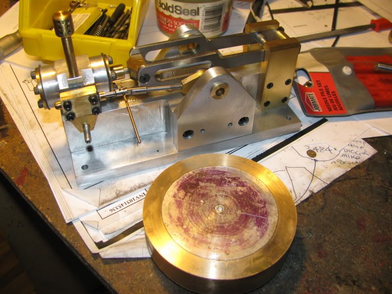
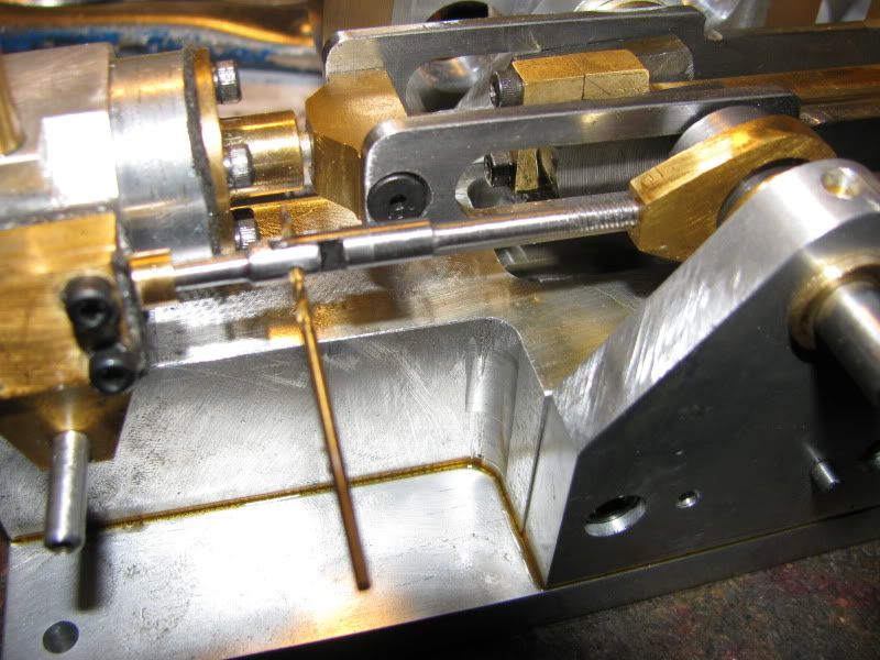
In case I never mentioned it---I HATE 4 JAW CHUCKS WORSE THAN SNAKES!!! I hate them worse than Canadian Winters!!!---And Damn, I really hate them when I make a cam thats supposed to have an 0.050" offset and somehow ends up with a .025" offset!!!
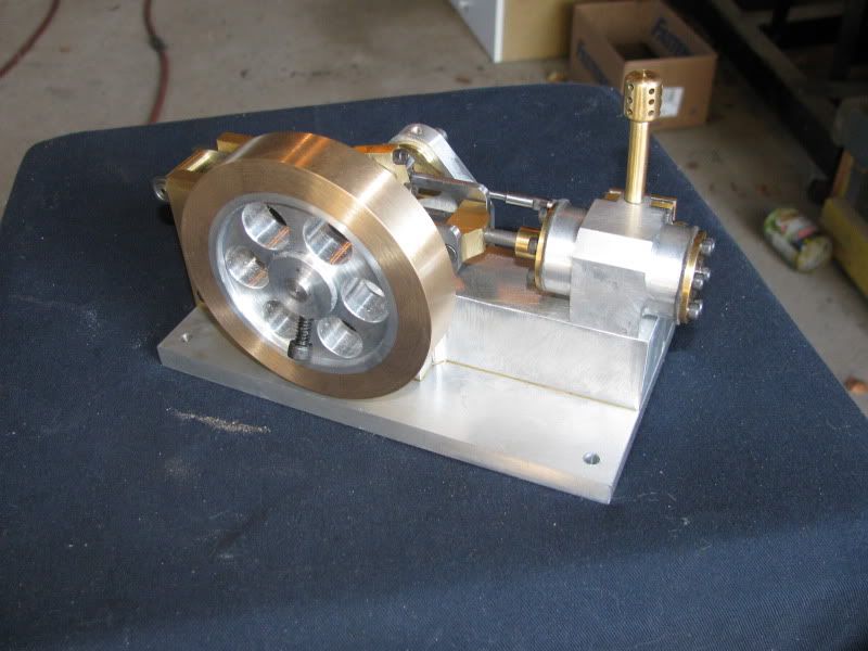
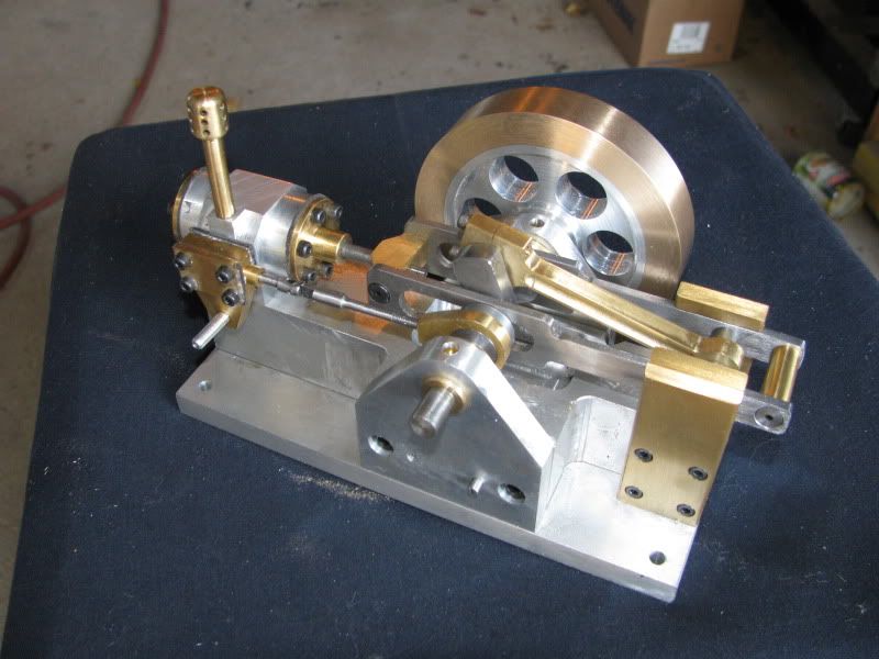
 
Not much to show for a hard days work!! A cam, the big end for the valve rod, and a rather be-snotted looking crankshaft. Why does the cam have a set-screw in both sides?---Because the end broke off the miserable 1/8" dia. c'sink, tool I had and I couldn't get it out---so I had to drill thru from the other side and push it out. This left me with an extra hole that I didn't want, so I just threaded both of them. One set screw will get a dab of Loctite and just be a "dummy" while the other does the actual holding work. I totally messed up my first attempt at the cam, but other than hurt feelings I survived it. That nasty crankshaft will get all cleaned up tomorrow and the extra bits cut off. In my heart of hearts, I only want to install that crankshaft once, so I wanted to finish all the bits that fit on or over the crankshaft today.
CAMANDCRANKSHAFT001.jpg
 
Well, Darn---That turned out nice!!! The crankshaft cleaned up beautifully, and seems very solid. The con rod is exactly per drawing, other than the fact that I bought a 3/16" ball nosed milling cutter this morning while I was out, and put a cosmetic groove down each side of the con rod.----I've never done that before. Can you believe that I only have two parts left to make!--A very small simple spacer for the end of the con-rod where it attaches to the overcrank mechanisn, and the flywheel. I am going to make a drawing of the flywheel as a one peice, turned from steel or brass. The reality however, is that I still have a big chunk of 3.5" o.d. heavy wall bronze tube left over from my kerzel build, so I will build a two part flywheel with an aluminum center, same as I did on the Kerzel.
CON-RODANDCRANK002.jpg

CON-RODANDCRANK001.jpg
 
I second what Dale wrote
That groove down the conrod sets it off beautifully.
with such clear drawings , I can see a few of these being built
Peter
 
The crank turned out great, Brian. And, that's a dandy looking connecting rod!

Chuck
 
Thanks guys. I just turned a peice of aluminum to the correct size and Loctited it into the bronze ring that I cut off the heavy wall bronze tube. Its time for me to buy a new pair of digital Vernier calipers. My micrometer only goes up to 1", and when I turned the aluminum to what was supposed to be a "light press fit" according to my current digital calipers it ended up being a "falling in fit". Damn!!! Issue was resolved by going around the perimeter of the aluminum blank and giving it numerous good 'whacks" with a center punch and hammer. This raised the material enough to get a good interferance fit, and so , liberally coated with Loctite 638 it will be ready to finish machine in the morning. Its going to be a heavy little bugger, but my gut tells me that with the added drag from the overcrank mechanism it will need to be.
FLYWHEEL-1002.jpg
 
good looking crank and con rod brian :bow:
sorry i could not help out with the tapered pins but as others have said you should be ok with what you did.

you might want to consider a set of 0 to 6" micrometers, there is a store in markham selling the set for less than $100.00.

chuck
 
Chuck--I like the ease and simplicity of a Vernier caliper, but they sure aren't the tool to be checking diameters with, unless "close" is okay. I very seldom turn anything larger than 1" o.d., so up untill now I have used my micrometer to measure when turning small stuff. My digital caliper has started to act erratic during the course of this build, so I am definitly going to have to buy something.
 
So---This is it!!! All the parts are finished. Now if I can only get it all together.---Jeez---I hope this thing runs!!!
FLYWHEELFINISHED001-1.jpg

FLYWHEELFINISHED002-1.jpg
 
Looks great.
It should run fine with that sized flywheel.

Pat J
 
Well kids----There it is assembled. All the parts fit. As expected, I have numerous binds and hard spots, but I will chase them down tomorrow. I'm just very happy that it went together so nicely.
ENGINEASSEMBLED002-1.jpg

ENGINEASSEMBLED004.jpg

ENGINEASSEMBLED003.jpg

ENGINEASSEMBLED001.jpg
 
Great looking engine Brian.

Looks like you are close to runtime.

Pat J
 
My digital caliper has started to act erratic during the course of this build, so I am definitly going to have to buy something.

That is usually a sign that the battery is on the way out.

The engine is looking good Brian!
 
For such a complex little engine, there are surprisingly few "set-up" adjustments. I have built all components exactly to "blueprint". The one design premise was that at the absolute end of stroke, the piston would be .031" from the end of the cylinder barrel (at either end of stroke). Since nothing else in the linkage has any adjustment built into it, the piston base mounting holes were slotted to allow making this adjustment. In the picture, you can see that I have the outboard cylinder head removed, and that there is about 1/16" space between the top of the piston and the end of the cylinder. I will loosen of the cylinder mounting bolts and move the cylinder untill I achieve the .031" that the plan calls for. This ensures that the piston will be truly centered in its travel in the cylinder. The other adjustment, and it is dependent on the first adjustment just described, is the slide valve position in the steam chest. When the piston is fully retracted into the cylinder as far as it can possibly go, the slide valve should be exactly centered between the two ports leading out to the ends of the cylinders. This of course, is why the end of the valve rod is threaded where it attaches to the large eccentric strap. A third variable is the exact position of the cam lobe in relationship to the crankshaft "throw", although that relationship should always remain "fixed" once it is initially adjusted. I think I made a mis-statement over on my "steam engine rotation" thread, so I must go over and remedy that now. If any of this information I just posted turns out to be an incorrect assumption, I will come back and edit this post.
enginesettings001.jpg

enginesettings002.jpg
 
This is what Elmer has to say about timing the #33 mill engine
At the final assembly turn the crank to one dead center position (full stroke either in or out of the cylinder) and tighten the eccentric with its axis 90 degrees from the centerline through the crank. Temporarily hold the steam chest in place while adjusting the valve to equally expose the valve holes at each end of stroke.
And I suppose that depending wheter you choose top dead center or bottom dead center to do this set-up is what determines the direction your engine will turn in.
 
If its at 90 deg it will run in either direction but not that well, better to give it 20 to 30 deg or so of lead in the direction you want it to run.

By admitting steam into the end of the cyl before the piston has reached the end you get a cushioning effect and a much smoother running engine.


J
 

Latest posts

Back
Top