Overcrank Single Cylinder Engine

Home Model Engine Machinist Forum

Help Support Home Model Engine Machinist Forum:

This site may earn a commission from merchant affiliate links, including eBay, Amazon, and others.
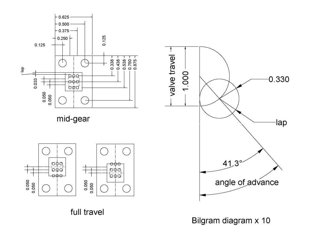
Brian, I drew out your valve assembly to scale and showed it through 135 degrees degrees of rotation. It looks like your inlet port is only open for about 90 degrees of rotation, between 45 degrees (second row down) to 135 degrees (last row). Wonder if maybe you need to increase the throw of your eccentric? Anybody else have any ideas in this area?

Chuck

ValveTiming.png
 
well sounds like you are leaving no stone unturned.
Tin
 
I FOUND IT!!!! At least I'm pretty sure I found it. I pulled the cylinder apart this morning for "Investigation and analysis". Remember when I drilled the bolt pattern in the ends of the cylinder way back at the very beginning, and the end broke off my c'sink so that I had to drill that one hole completely thru from the far end of the cylinder to pop the tip of the broken c'sink out and tap the hole at that end. Well that long hole intersected with one of the four tapped holes which hold the steam chest in place, and break thru into the cylinder body. This acted as an air bleed internally in the cylinder body. I just epoxied a peice of .093" diameter steel rod and plugged that hole in the center with it, leaving the thread at both ends for the bolts that hold the end caps on. Cross your fingers.---This may have it!!!
 
Brian,
You most likely found the problem however I had nearly finished my study of the valve gear for this engine, so I thought I might as well post it.

From the drawings we know the valve travel it is twice the eccentric throw or 0.1". We can also use the drawing to determine the lap of the valve which is 0.033" if I made the drawing correct. The angle of advance is the the angle that the valve leads the crank plus the normal 900 the valve leads with no lap. The other thing that affects the angle of advance is the lead. To make things simple I am assuming the lead is zero, this is a common assumption for model engines.

Now we have enough information to construct a Bilgram diagram to calculate the angle of advance for the valve. The valve diagrams are really graphical calculators. I favor Bilgram because they are simple to construct and the true reason is it is the first one of the diagrams I figured out and it was wonderfull when the light went on.

Briansreturncrank1.jpg


I got 41.30 for the angle of advance so we add this to 900 to get 131.30 that the valve leads the crank in the direction of travel. I also draw the valve at the limit of travel to show what the valve looks like at full travel. The ports do not fully open but some designers use under travel so I can not say that it is wrong for this engine.

If there is any interest I can do a thread explaining Bilgram's diagram.

Dan
 
It just realized why the steam ports are only half opened. The normal scheme is to meke the exhaust twice the area of steam supply. If you use the same size drill for all the holes this is a clever way to make the exhaust area twice the inlet area.

I am asuming that this is the valve for Elmers 33 so what did he say for the angle of the eccentric?

Dan
 
I know that a number of tapped holes break thru into the cylinder bore.

What kind of engine has tapped holes breaking into the cylinder? Looking at #33 plans in Elmer's Engine book, I don't see any holes penetrating the cylinder.

Since you claim to have these holes, I would inspect them very carefully. It's quite possible you've created a path for pressurizing the top of the piston when it shouldn't be.
 
Some how, in some way, I have angered the machining Gods. Having tried everything else, and not having success, I just went down to my metal supplier and bought a foot of seamless steel mechanical hydraulic tubing. I am going to hog the cylinder bore out to 11/16" diameter and Loctite in a liner, then ream the liner in place. Yes Marv, you are right. Elmers plans didn't call for any tapped holes breaking into the cylinder bore. I did that on the Elmers 33 that I built because I couldn't figure out how else to tap such short blind holes.---And I got away with it. My bad---I'm learning as I go along here. I didn't get away with it this time. The holes which break thru into the cylinder bore are leaking air from end to end. I consider myself duly chastised and won't make that mistake again. Sometimes I wish I was smart instead of good looking!!! Stay tuned.----Brian
 
So this is my save for today. The steel tube I bought was .750" o.d. x 0.610" i.d. I turned the o.d. to .688" and while in the same set-up in the lathe I took a skim cut off the i.d. with a boring tool, then finish reamed it with lots of oil and a .625" reamer. My initial thought was to ream it in place after it was installed in the cylinder, but decided for the sake of concentricity to turn the o.d. and the i.d. in one set up. I cut the tube to length 3/32" shorter than the length of the cylinder, to allow for the intrusion of the ends on the inside of the cylinder caps. I also filed a v-groove in both ends to line up with the holes in the cylinder that let the compressed air into either end. I set the cylinder up in my milling machine and bored it out to .689"
http://s307.photobucket.com/albums/nn294/BrianRupnow/?action=view&current=CYLINDERLINER002.jpg
CYLINDERLINER001.jpg

 
And here we are with the cylinder liner Loctited in place with #638 Loctite. I washed both parts with methyl alcohol before installing the liner to wash away all traces of oil and grease first. Tomorrow I will hone the i.d. of the liner with my brake cylinder hone to give it a somewhat smoother finish than the reamer leaves.--And yes, I did clean that loctite out of the tapped hole.
CYLINDERLINER003.jpg
 
Old age and treachery triumph once again!!! I got up early this morning, machined a new closer fitting piston from brass and lapped it into the cylinder with #400 and then #600 lapping compound. That extra flywheel on there was not necessary, it was still on from yesterday, but the engine is now setting here on the corner of my desk chugging away without the extra flywheel. The only change necessary to the drawing of the cylinder is that the tapped holes must not break thru into the cylinder bore. Or else do like I did and install a liner after the fact. The slide valve is obviously working just fine. In the video, the engine is running on 40 psi, but I expect that after it runs for a while it will run on less. after I let it run for a couple of hours I will clean it up and post a better video.----Brian
 
Congratulations. It's a very attractive engine.

Now that it's done you have an opportunity to spend some time learning how to tap small, blind holes.

When you break a small tap, regrind the tip into a bottoming tap if there's enough meat left to do that. (If not, just make a tiny boring bar out of it.)
 
CONGRATULATIONS !

I have followed this with much interest since day 1. It will be my next build after I finish "Gerry's walking beam" engine. Looking forward to your final prints.

Larry
 
Congratulations Brian on another wonderfull build by you,and thank you for shareing your vast tallent .

best wishes,
Ian(seagar).
 
Congratulation Brian

A very very nice engine, beautifully drawn and made.

I'm shure it will become a build for many people.

Stew
 
Now, if I have remembered how to do this correctly, clicking on the link will get you a download of all the drawings in .pdf format from MediaFire. They will be in a .zip file. Click on the "start download" link and select "save" and it will ask you where you want to save it to. After you have saved it to somewhere on your computer, double clicking the file should open it and make all the drawings accessable. If anybody sees any glaring errors or omissions, please let me know.
http://www.mediafire.com/?s1wx05r8347s2y3
 

Latest posts

Back
Top