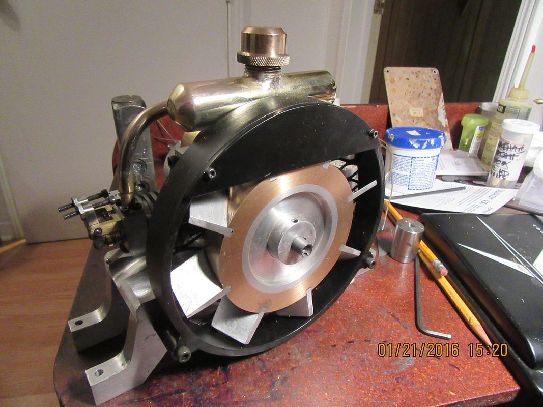
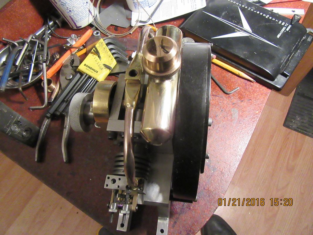
Opposed Twin I.C.

Home Model Engine Machinist Forum

Help Support Home Model Engine Machinist Forum:

This site may earn a commission from merchant affiliate links, including eBay, Amazon, and others.
Looking mighty fine but I think the stacks need their angle cuts.
I agree Cogsy--I won't cut them though until I get the intake system sorted out and installed, because the intake system is going to visually have some effect on just how long the stacks should be.
 
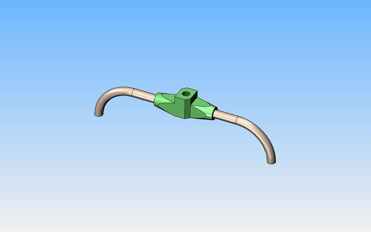
It is time now to give some serious consideration to the induction system. On my original model, I had one tube with a 90 degree bend only, the other tube had a 90 degree bend as well as an offset. Since I am using the two cylinder ports which are closest together as intake ports, this means that the offset is minimal. If I set the intake up like this, I can make both intake tubes identical, and make the central carburetor block where the intake tubes come together with an offset incorporated into it.--I'm not sure about this yet.--I may find that the brass tube is easy enough to bend that I will use my original idea.
 
Today I made some progress on the intake system. I didn't use brass tubing. I picked up a length of copper-nickel automotive brake-line, which bends very easily without flattening or kinking, and it seems to be exactly what I needed. This is the main part of the intake roughed together but not soldered yet. I decided to go with my original idea for the brass centerpiece and bend an offset in the right-hand side bent tube.
 
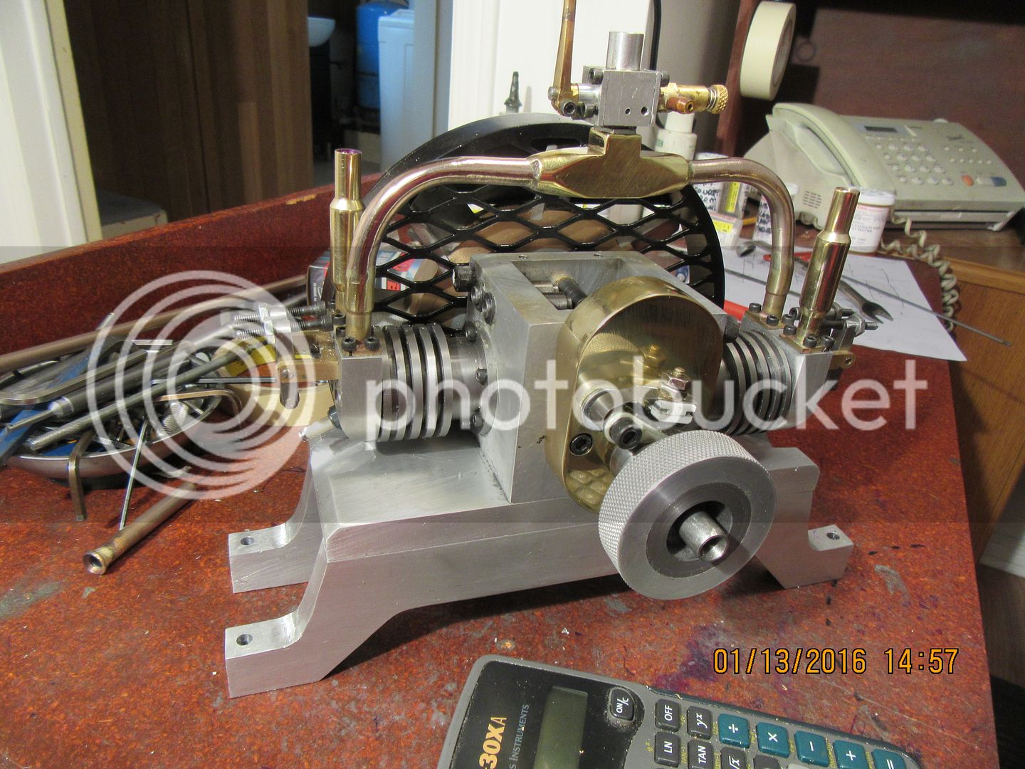
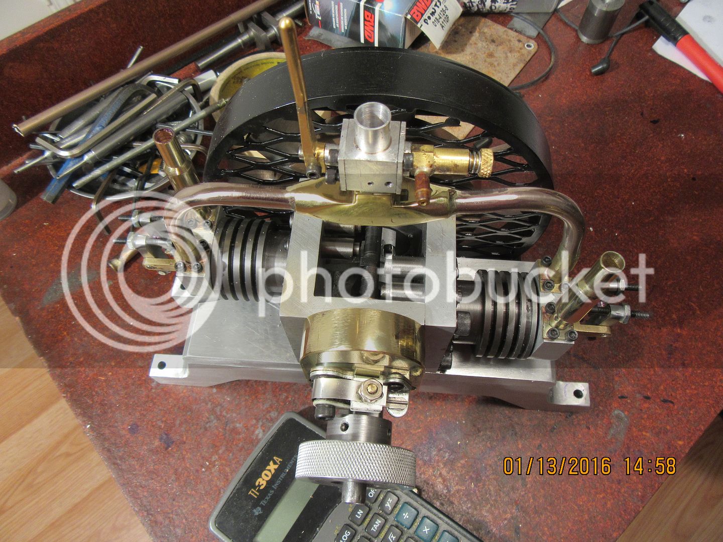
I've been a busy guy the last couple of days. The intake system is all soldered together and polished.--I really hate polishing things like this. There are just so many sharp corners and angles to catch on the spinning buffing wheel, rip it out of your hands, and fling it around the room.--You immediately have to stop and count your fingers when this happens!!! Fortunately, I still have all of mine, albeit gouged up in a couple of places. I borrowed the carburetor from the Canadian Cub, as I can always build another carburetor after this engine is up and running to replace it. I chickened out on the enormous exhaust stacks. They looked too "cartoonish" for me.---Like something out of a 1960's "Trucking" magazine. I took Jason's advice and reworked them into "stacks with mufflers". My old digital camera did die, just like I thought it was going to. I had to go down street yesterday and buy a new one, and judging by the pictures shown here, it works pretty good. I'm waiting now for the Loctite 620 to come in so I can finish up the valve cages into the heads. We are getting close to the finish line now, and it's getting exciting. So far I have followed the 3D model quite closely. I may rethink the position of the gas tank, but I'm not sure yet.

 
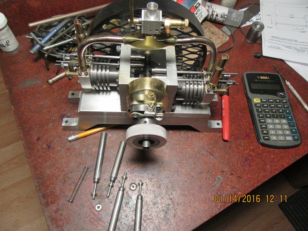
This morning we have pushrods and valve spring "keepers" (shown on the valves setting in front of the engine). The pushrods are made about 1/2" longer than their finished length will be. I will trim them to the correct length after I get the valves, springs, and keepers and cages installed in the cylinder heads.
 
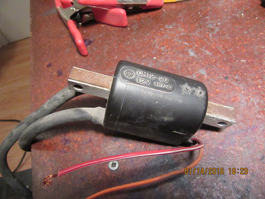
I picked up a used 12 volt dual output ignition coil today from a local motorcycle shop for $10.00. We tried it out at the dealers, but the spark seemed very very "wimpy". We tried out about four different used coils and this was the only one we had any success with. It was giving a spark from both ignition wires, but it was pretty feeble. I don't really know how well the battery was charged at the dealers when we tried out the coil.----So---I brought it home to try it out on my 12 volt battery, and wouldn't you know it, my 12 volt battery was dead!!! So, now my battery is on the charger, and all I can do is wait for it to charge.There are two high tension cables coming out of the case, and two small gauge wires, one red with a white stripe and one solid orange. I am assuming the red wire with white stripe is the positive feed, and the orange is the ground to complete the primary circuit. I don't have any prior experience with dual output coils, but I'm sure the sparks from the high tension leads, when it's ran off a fully charged battery should be big fat blue ones, not anemic yellow ones. If the coil is no good, I'm only out $10 but I'm hoping that after the battery is fully charged I get better performance from the coil.
 
I think there needs to be a chunk of iron connecting the ends of the iron that
the coil is wrapped around for the field to form correctly. I suspect that the original
mounting did that. ????

Pete
 
I went out this morning and borrowed the 12 volt battery from my lawn tractor. With everything hooked up, I am back to getting a pair of very anemic sparks from the high tension leads of the dual output coil when I momentarily connect, then disconnect the low tension leads. I don't really buy this bit about the condenser giving a stronger spark, but I have been wrong before. I have to go out in about 10 minutes to quote a job, so I will pick up a new points and condenser while I am out, as I will eventually use them anyways, and that will give me a condenser to wire into this "try-out" circuit. I'm not sure about the mild steel mounting bracket having any effect on the magnetic field either, but I will make one up to see if it makes a difference. I am basing my negatives on the fact that when you hook up a 12 volt automotive coil as I have this dual output coil, it will give a fat blue arc half an inch long, without benefit of condenser or mild steel bracketry.
 
I don't really buy this bit about the condenser giving a stronger spark, but I have been wrong before.

the condenser will not give you a stronger spark, it's going to save your point cause it's cutting the magnetic field and because it oppose itself to a current change it will give you a longer spark then your point would.

I'm not sure about the mild steel mounting bracket having any effect on the magnetic field either, but I will make one up to see if it makes a difference.

the bracket has nothing to do with it, you already have the piece of metal you need for your core.

I am basing my negatives on the fact that when you hook up a 12 volt automotive coil as I have this dual output coil,
remember Brian this coil CAN give you a spark at both lead at he same time but it won't on your engine cause one cylinder will be lean and the other one fat. to duplicate that and see the real output of your coil ground one HT wire when doing your test.

Cheers
 
I just wired a condenser into the circuit, and as I expected, it really didn't make any difference to the spark from the high tension leads. I was taught that a condenser is in the circuit for the following reason, and has nothing to do with enhancing the ignition spark. When the current flow to the primary windings of the coil is interrupted by the points opening, the collapsing magnetic field induces a current flow in the secondary windings to produce the spark. The fact that the magnetic field is collapsing also induces current flow in the primary windings, and this current flow has to reach ground---However, the points have just started to open, breaking the circuit and creating the induced current in both sets of windings. The current induced in the primary windings will jump across the newly opened points to reach ground. This arcing will soon break down the contact surface of the points and "burn the points out". However, if there is a condenser in the circuit, this induced current in the primary windings will flow into the condenser and be slowly bled off to ground instead of arcing across the points contact surface.---At any rate, I am getting consistent anemic yellow arcs from the high tension leads. I would like to know more about this mild steel bracket that supposedly enhances the operation of the coil. I suppose that since I have to mount the coil somehow, I can incorporate a mild steel bracket into the mounting to see if this is a real or imagined benefit.
 
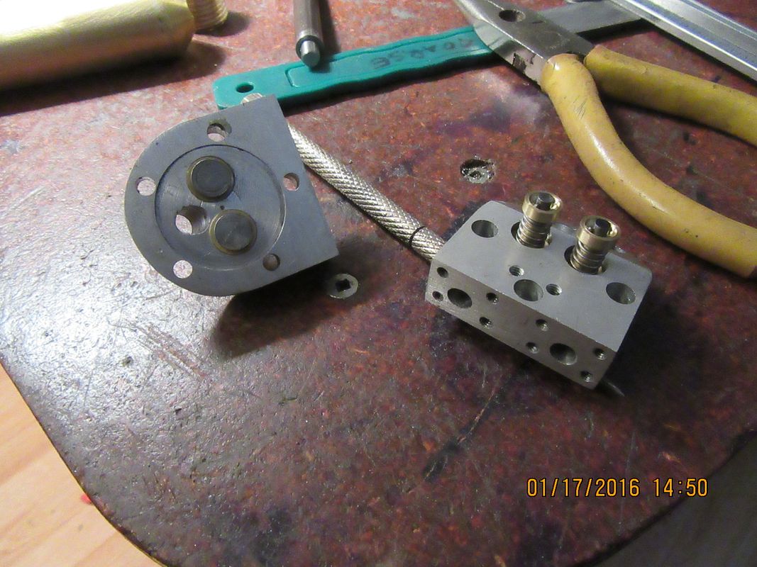
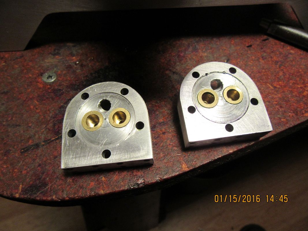
All four valve cages have been liberally coated with 620 Loctite and pressed into the cylinder heads. "Press fit" is kind of a nominal term. You can't make it a hard press fit, as the cages will distort from the pressing. On the other hand, you don't want them to "fall" into the holes in the head either. Every time I build one of these engines, the fits end up a little different. I had two cages that couldn't be pressed in by "hand" and two that fit so poorly I went around the perimeter with a prick punch to upset the metal and increase the diameter a bit. This 620 Loctite retaining compound is a new one for me. It has a much higher temperature rating than the #638 that I have always used before. You will notice that I haven't put any chamfer on the seat portion of the cages yet. I will wait 24 hours for everything to set up good, then drill the passages that go through the cylinder heads and the sides of the valve cages, and then I will use my "George Britnell seat turning tool" by hand to put in a 45 degree x .015" chamfer on the area that the valves seal against.
 
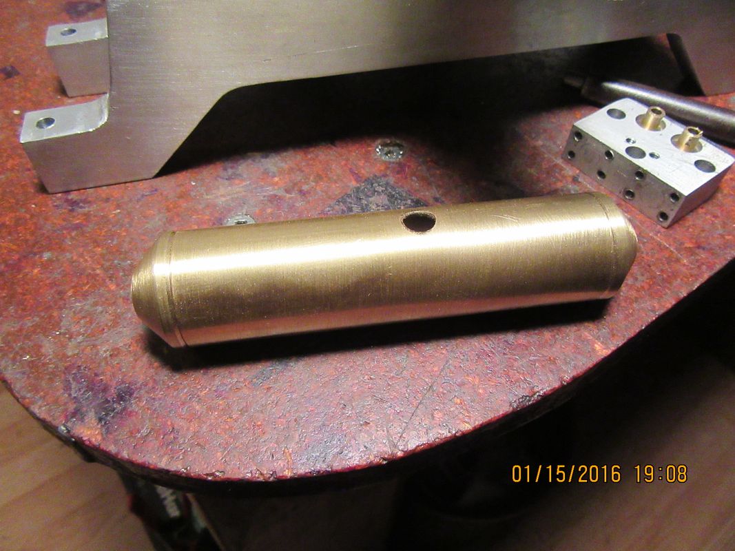
I'm down to my very last piece of 1" brass tubing that I salvaged from a pole-lamp about 5 years ago. That lamp has certainly made a lot of gas tanks over the years!!! Unfortunately, I gave away my Steve Bedair type ball turner, because I never used it, so the gas tank ends are going to have a slightly different shape than the tank in the 3D cad model.
 
If we go with the assumption that this engine may run someday, at least we now have a place to put the fuel. I haven't put in the outlet nor the support bracket yet. I will wait until I have the engine all back together before I finalize that part of the gas tank.
 
Voila'!!! We have valves cut to length, lapped and installed. The keeper pins setting in the top of those valve keepers are only 0.039" diameter. I will have to check each valve individually to make sure they have enough travel between fully open and fully closed. The total "lift" on my cam shaft is 0.067", and I must have at least that much travel + 10% total movement possible on my valves.
 
Hi Brian,
After reading your issues with the ignition coils, i've started experimenting with a few i got at home.
I had a strong spark once i figured out the wiring.
Your coil is a genuine Yamaha part (4h7-61).
Those coils attach directly to the bike frame, needing battery ground on the metal bar.

After watching a few wiring diagrams, i think you would need to wire the battery negative terminal on the metal bar and contact points should go on the red cable.
The orange should be for engine stop or RPM measurements.

I'm not sure if the coil you have is for a TDI (not CDI) ignition system. If that's the case, it won't work without an actual TDI ignition controller and supplementary coil.
TDI systems require a special stator coil to work.
Look at the coil with black tape on the stator below.
http://mla-s2-p.mlstatic.com/estato...pton-110cc--15129-MLA20096844517_052014-F.jpg

Hope this helps

Norberto
 
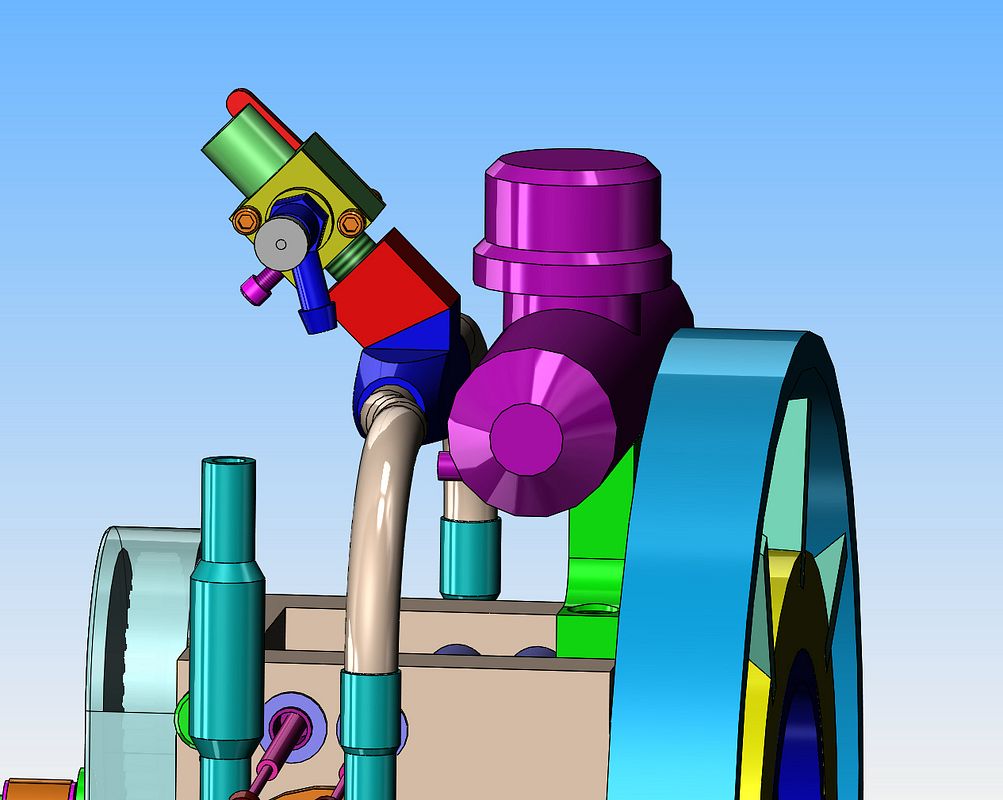
I've had to back-track a little bit and add a piece between the intake manifold and the carburetor (the red part) to move the carburetor a bit to make more room for the gas tank. Although it looked okay on the original model, there were just too many things fighting for space. Also, I wasn't really comfortable with the carburetor air intake being right tight beside the gas cap on the tank. I have seen those carbs backfire and spit out a flame, and positioned right tight to the vented gas cap would not be a good thing.
 
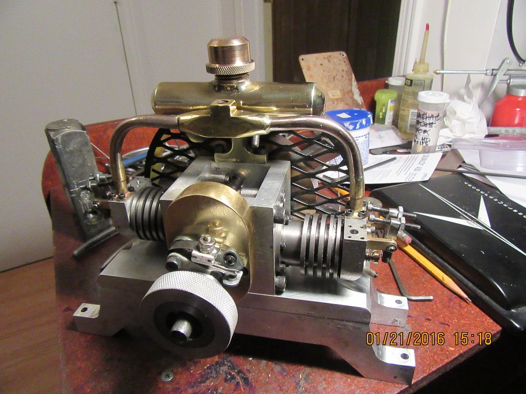
And now you know what I've been doing the last few days!!! I swear to God, there is more work in that gas tank than there was in the first two engines I built 6 years ago!! And yes, there is a gap between the gas tank and the black painted flywheel shroud. It's only about 1/16", but it is a gap.--Which is light years better than an interference. The only mechanical thing I have left to make is the red offset bracket to move the carburetor over a bit as shown in the previous solid model.


Latest posts

Back
Top