Opposed Twin I.C.

Home Model Engine Machinist Forum

Help Support Home Model Engine Machinist Forum:

This site may earn a commission from merchant affiliate links, including eBay, Amazon, and others.
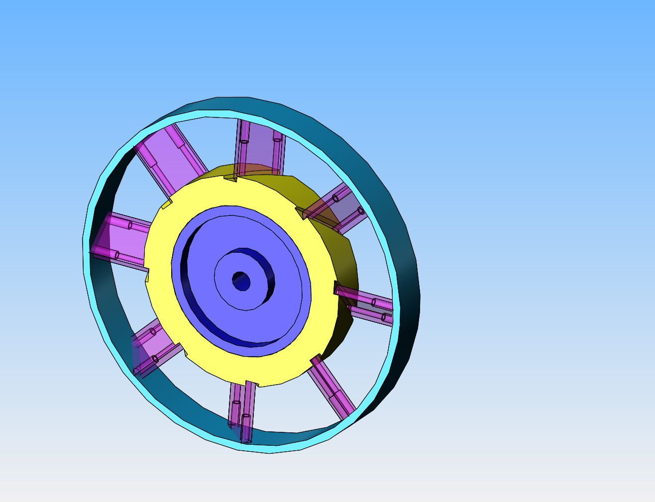
This vaned flywheel is getting more and more interesting. I'm kind of making it up as I go along. I'm pretty sure I can set the rotary table at 45 degrees to the long axis of the table, mount the bronze ring on the 3 jaw chuck holding it from the inside and using a 3/16" endmill run the table back and forth in X axis to cut the slots 3/16" wide x 1/8" deep. Then drill and tap the two #2-56 holes in the bottom of the slot.--Then rotate the rotary table 45 degrees and repeat---eight times in total. The vanes would be from 3/16" x 7/8" flatbar, drilled and counterbored for #2-56 socket head capscrews. The end of the flatbar closest to the center would just be a flat 90 degree cut. The cut at the other end however, will take on a strange twisted shape if it is going to be full contact with the inside of the outer rim. They will be brass, so MAYBE I can cut them .050" long, then bolt them to the bronze hub, press in the center, and then take a skim cut on the outer ends of the flatbar with the lathe to bring them down to final size.
 
Could you have used an old computer cooling fan if you didn't want the pretty version?
 
Could you have used an old computer cooling fan if you didn't want the pretty version?
Yes, I could have----if. Right now I have two or three i.c. engines I have built and posted on this forum about that run either small plastic fans or fabricated brass fans, driven by an o-ring drive off the flywheel. I have my heart set on this "pretty" version, but it may not happen. I can see my way clearly up to the point where I have to attach the outer rim. That is problematic. I may make up everything but the outer rim. That would create a dangerous finger chopper, But--If I ran it in a close fitting "fixed" shroud it would still have the same effect in terms of creating airflow over the cylinders, be safe in terms of chopped fingers, and be one heck of a lot easier to fabricate.
 
Okay---Maybe I'm onto something a little more realistic. The flywheel with vanes revolves--the outer rim has become a fixed shroud. Much, much easier to fabricate.--Finger safe, and still provides cooling air.
 
I like the separate rim/shroud idea if interested in protecting fingers. I'm of the school of "don't put your fingers there", but that has backfired on me.
 
I have seen Ingersoll-Rand air compressors coming into Singapore in the 60s 70s with Open BeltGuard,Semi-Enclosed B Guards and fully enclosed BGs and all not finger proof. In the 80s 90s 00s all BGs were finger proof. There were some native workmen South Africa who would poked their fingers thru non-finger proof BGs to claim big compensation. Gus would never work on compressors with BGs removed. Just very scary.

HMEM folks.Please take care.
 
Making it up as I go along---the rotary table mounted at 45 degrees to the X axis on the mill and a 1/8" four flute endmill did the job just as I hoped it would. The slots are 3/16" deep x about .130" wide. While in the same set-up I drilled 1/16" holes thru on center of each slot. I then Loctited 1/16" cold rolled round rod x 1" long into the holes, with 1/2" exposed. I made up the 8 "vanes" from 1/8" thick aluminum and drilled a blind 1/16" hole 0.7" deep in the center of each "vane". I knew that the .125" vanes were not going to fit tightly into the 0.130" wide slots----but I had a plan. After trial fitting everything, I got out my old friend J.B. Weld, mixed up a batch, and filled one groove at a time and coated the exposed portion of 1/16" cold rolled, then tapped the vane into place until it was seated. Right now the bronze ring and the aluminum hub are both 1/8" wider than the planned 3/4" finish width. It is my greatest hope that after Loctiting/pressing the aluminum hub into the bronze ring (I have decided not to use heat shrinking) that I will be able to grind a really sharp tool and face both sides of the aluminum center, the bronze ring, and the sides of the vanes without everything turning to crap.

 
That is a really neat way to make a flywheel with vanes...awesome.
 
Here we are at the lumpy nasty stage. The vanes are secured with a large pipe clamp. The aluminum hub is a "Damn that's close/Loctite fit". After a night of curing, it will be into the lathe and either be the "Oh Wow--Look how good I am" stage or the "Oh Poop!! Start over again" stage.
 
Last edited:
Machining of flywheel with vanes attached went very well. The vanes never gave any indication that they might want to come off. The biggest challenge I had was that 660 bronze hub wanting to suck the tool into the work while facing it. I am putting this down to the fact that the shaft everything was mounted on was only 3/8" diameter, and once the tool tried to suck into the bronze the shaft would deflect a bit, then spring back, leaving a series of evenly spaced divots around the face of the bronze. I tried every machine speed and tool angle and sharpness, but nothing made any difference. Thankfully the divots were shallow enough to mostly come out with some 160 and 220 grit emery cloth. The aluminum vanes of course came out razor sharp, but some light file work knocked the sharp down a bit. I definitely won't be running this flywheel without a full surround shroud.
 
I resorted to a little hocus pocus when I designed the bushings for the crankshaft and camshaft. I wanted to be able to pull the crankshaft or the camshaft straight out of the engine without splitting those two main frame angles. So---I have a large "bushing insert" with the bushing pressed into it, bolted into a counterbore in the frame angle which supports the end of the crankshaft closest to the flywheel. If I remove the flywheel and the blue "bushing insert" the entire crankshaft should pull straight out through the side of the housing. I did something very similar at the opposite end of the camshaft, only there the bushing itself has a large enough outer diameter that by unbolting it and pulling it out, the whole assembled camshaft can be pulled out thru the side of the main frame.

Hi Brian
I stumbled across your post, and thought you might like to know that this is just how the crank goes in / out of a flat twin motorbike engine (with con rods in-situ) - but I guess that's where you got the idea from. I run a 70s 'Ural' 650cc bike made in Russia, which looks a lot like a BMW (for historical reasons I won't bore you with). I bought it in big rusty lumps with a seized big end, and even with the rear main bearing carrier plate removed, the seizure meant the con rods wouldn't fold up (to BDC) to allow me to roll the crank out through the resulting aperture. Lots of unsympathetic con rod bashing with a big hammer was the only way forward :)
 
Hello Brian,
Like your design work and in particular your opposed twin IC design. Want to raise a point though about the way you made or rather attached the vanes to the fan wheel / fly wheel center using a combination of JB weld and some 1/16" dia. pins.

I know the rpm of the engine will be low but I have a concern about the limitations of the retaining forces that will try to restrain and hold in place the vanes against the centrifugal forces that will try to pull the vanes outward. I don't know how well the JB and the 1/16" pins will be able to do that short or long term since the centrifugal forces apply in shear to the JB weld / vanes and 1/16" pins.

Instead of having the shroud a separate piece of the fan / fly wheel I believe it would add to safety by making the shroud an integral part of the fan assembly.

Like your work and creativity!

Peter J.
 
Peter--Your concern is noted. I was going to attach the outer rim to the vanes, but simply couldn't come up with any good way of doing it. The vanes are only 1/8" thick. I have no concerns about the Loctite in shear. The JB Weld I'm not so sure about, but the end of the vanes are only 0.100" from the inside of the stationary shroud. The flywheel is only 3/4" thick, the shroud will be the same width.
 
Now that, my friends, is a piece of angle!! I had to go across town yesterday to pick up some Destaco clamps for a customer project, and one of my metal suppliers is almost next door. I stopped in and asked if he had any offcuts of aluminum angles with 1/2" thick legs. He answered "Yes, and I've been saving it just for you!!!"---It is a piece of aluminum angle 8" x 8" x 1/2" x 10" long. Far more than I need, but there is a lot of good 1/2" material that I can salvage from it after I cut out what I need for the engine frame.
 
I haven't abandoned this project.--It's just that I've been so busy with other projects----. Tonight I stole an hour to add all the bolt holes into the two main frame angles and show the four 1/4"-20 bolts (green-two each side) that hold the angles together.
 
After a summer of "relative" idleness, my business commitments have exploded to the point where I have no time to build my own stuff!!! I did steal some time this afternoon to walk out to my converted bandsaw with that HUGE chunk of aluminum angle, and reduce it to smaller pieces, close to what my engine's finished frame size will be.This great flurry of real work will only last for a couple of months and then die down just before Christmas. After the struggle I had unloading and setting up my new lathe by myself, I decided to call a local machinery moving company and ask for a quote to move my old lathe out from my machine shop into my big garage, and move my new larger lathe from my big garage through my office into my small machine shop. They quoted $500 which seems like a lot, but I think some of the money from my current "real work" would be well spent having them do this. Both lathes are quite top heavy, and if I tipped either of them over while moving them, that $500 wouldn't seem like very much!!!
 
Hi Brian,

Paul Swift,
Received a call at 5.45 am and going for Kidney Transplant. Please pray for successful operation.
 
This morning I have made the unsettling discovery that aluminum angles aren't really 90 degrees on the outside. In fact over a 2 1/2" leg. they run out as much as .030". I can clean this up, it's not a deal breaker, just a surprise. I wonder how much things will spring out of square when I machine away that rolled in inner radius? I think I will get rid of the inner radius first, see where things spring to, then clean up the squareness.
 
So there we have it. An absolutely fabulous way to spend a Saturday. The frame pieces are cut to size, the radius is machined away, and the main frame bolts and dowel pins are in place.
 
Back
Top