Oilfield "Pumpjack" model plans

Home Model Engine Machinist Forum

Help Support Home Model Engine Machinist Forum:

This site may earn a commission from merchant affiliate links, including eBay, Amazon, and others.

Looks good Brian;

If you get the critical geometry nailed down, a guy could fancy it up as much as he pleases.

this one looks shiny;

[ame]http://www.youtube.com/watch?v=lzEzx227hL8[/ame]

and another from the same company;

[ame]http://www.youtube.com/watch?v=Yyju3IA3kP0[/ame]


Thanks for your time.

 
Maybe it's just me but a blinged-up oil derrick and pump just looks sooo wrong. It reminds me of a dump truck with chromed bumpers and mag wheels.
 
mklotz said:
Maybe it's just me but a blinged-up oil derrick and pump just looks sooo wrong. It reminds me of a dump truck with chromed bumpers and mag wheels.

Kinda like "Pimp my Oilpump"---right Marv!!! ;D ;D ;D
 
I recall seeing these oil pumps decorated with plywood and paint to look like animals.

I most likely saw these in California in the 1960's.

No..... I was not using drugs then. 8)

SAM
 
I recall seeing these oil pumps decorated with plywood and paint to look like animals. I most likely saw these in California in the 1960's.

No..... I was not using drugs then.

SAM
 
Yeah, they were... like... groovy... you know, dude? :)

The best one I remember was one fixed up to look like one of those "dipping bird" toys we all had as kids.
 
Brian Rupnow said:
As far as ratio and proportion is concerned, it reflects what I have "seen" in pictures, as I don't have one in my back yard to measure (Darn it!!!)

Brian; I wouldn't get to concerned with dimensions or ratios. There are so many different models, types and sizes of these things that you are bound to be close to one of them. Your proportions look about right to my eye and as long as it looks good to you it should be fine.

Any details you want photos of just ask. There are several near by and lots of equipment dealers with new ones out in their lots.

A number of them have the top beam made of "I" beam or 2 "C" channels back to back. That would be pretty easy to fabricate / replicate.
 
The model engine Gods have smiled on me once again!!! I went over to Ideal Hobby in Barrie, and found some very inexpensive gears that I am sure will work fine for the pumpjack model. The large gear is a nylon composite 32 pitch 72 teeth with a 0.220" wide face, and (fortunately) no hub. I say fortunately because the pinion is an 11 tooth metal gear with an offset hub and a bore of only 0.125". But---for a total cost of less than $10.00 Canadian, I can work around that. I know these gears are available all over North America, and may be available worl wide. (I hope so, anyways). The big gear is made by Traxxas and the small gear is made by Robinson Racing Products.
GEARS002.jpg
 

That's funny, I was thinking of the same large gear as I have several spares for my Nitro truck.

Nice choice!

 
There we go!! I had to do a few terribly clever things with the gears (and add a second pinion gear) to get clearance for a large enough diameter pulley and not have it hit the counterweight shaft. However, all things seem to have worked out fine, so tomorrow I will start with the details.---Brian
OVERALLPUMPJACK-1.jpg

blowupofgeararea.jpg
 
For anybody who is really "Itching" to build this pumpjack, here is something to get you going. I am going to post the things that are 99% sure to not change as the build progresses.
TOWERSPACER.jpg
 
Looking real good there Brian, and I commend you on your CAD skills as well. It is nice to find bits that can be of practical use in the hobby stores too. I *think* that both of the companies mentioned have products worldwide. Can't wait to watch your prgress.

BC1
Jim
 
Brian,

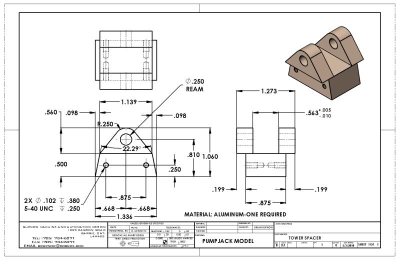
Very nice drawings indeed, and I am not nitpicking at all. Because your drawings show the correct dimensions with allowances made for the angles of the faces.

But some people can make a mistake sometimes by not showing the dimensions for the correct end to take your measurement from for machining the part, and because yours has both shown to perfection, I thought I would take the opportunity to explain a problem that can and does occur.

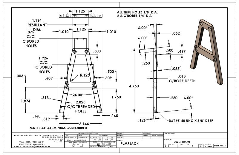
The part of your drawing shows a very good example, in that it has two different angles on it, both acute (from 0 to 90 degs) and obtuse (from 90 to 180 degs).

This can lead to a common mistake by machinists who are new to this game, and it isn't an obvious one, even though it would be obvious to many of us more experienced ones.

If you try to take an edge finder reading from the obtuse end (larger than 90 degs), your dimensions will be incorrect when you come to drill the holes, as your edge finder will be picking up the face lower than the corner rather than exactly on the corner, which would not happen if you used the acute end.

How do I know this? I can still remember the clip around the ear from my instructor over 40 years ago. They could use corporal punishment in those days.

Just to try to explain, I have shown a red arrow pointing to the acute angled end, which should be used for taking your measurements from.


Bogs


working end.jpg
 
Bogs---You are absolutely right. I have to assume when doing these drawings, that the folks who are building from my plans have progressed far enough in abilities as a machinist to know some of this stuff.--And as you point out, if they don't know this now, they will figure it out pretty quickly. My mandate here is not to teach novices how to read drawings, but to provide drawings for machinists from rank "newbie" to experienced senior gentlemen who have been machining and reading drawings for half a century.----Brian
 

Latest posts

Back
Top