Model Sawmill Dreaming---

Home Model Engine Machinist Forum

Help Support Home Model Engine Machinist Forum:

This site may earn a commission from merchant affiliate links, including eBay, Amazon, and others.
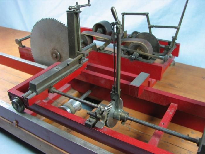
Check this video out!!! The commentator gets a bit fumble mouthed a couple of times, but it does give an excellent video of the operation of the saw and carriage advance mechanism on this type of a mill. It also shows (and I hadn't thought of this) that the ratchet/paul mechanism can be used to back the carriage up. Now I have to watch that reverse action a couple more times, because it only shows it for about a second. EDIT--No, I had that wrong.--There is a counter rotating friction wheel engaged by a lever that backs the carriage up. I don't know why there isn't any sound on the video. There is on the original which I copied and pasted the link from.
[ame]http://www.youtube.com/watch?v=XRK0aD6-OhY&feature=relmfu[/ame]
 
Last edited:
So here we have it, boys and girls. Enough aluminum to build everything I have detailed so far, plus 24" of rack and two spur gears, for the grand sum of $136.00----The rack and two gears cost $90.00, which included shipping and tax. The aluminum cost $46.00.
RACKGEARSANDALUMINUM003.jpg

RACKGEARSANDALUMINUM004.jpg
 
Brian, your ability to take an idea and put it on paper is nothing short of amazing. I always watch your builds and have learned a LOT. Thanks for sharing your expertise with us.
 
Brian, I was going to say you were having a busy Thanksgiving, but then I remembered i was a month late. :)

The parts are looking good as usual.

Pat
 
Well, its been a long hard day at the Rupnow Sawmill Works, but the crew is happy. We have the sawframe ready to rock and roll, all except for a blade. This is the first full day I've had off from my "real job" so I figured to "Make hay while the sun shines". The little brass wheels inset into the sideframes are intended to eliminate some of the friction between the sawframe and the two towers that it rides in as the log is forced into the sawblade by the carriage.
SAWFRAMEFINISHED002.jpg

SAWFRAMEFINISHED001.jpg
 
Good work! That video was interesting showing the reverse feed. I wonder how they stepped the log over for the next cut?
 
Bret--that is one of the things I have never been able to figure out from any of the videos. In fact, it appears as though the logs are TIED onto the carriage, which I simply can not believe. There must have been some kind of machanical linkage, similar to the one shown earlier in this thread as designed by GBritnell, but I haven't seen one anywhere.---Brian
sawmill202.jpg
 
Last edited:
This morning we will do something a bit different for a change. My 100 tooth change gear has a bore of 20mm. I have to build a hub for it that will go onto a 1/4" shaft. I don't want to destroy the change gear in any way, so I will build a hub from a crusty old 3/4" fine thread bolt (which has already been modified at some point in its past, note the round head). 20mm is 0.787". That means I will have to build a spacer with a wall thickness of .018" and an i.d. of 0.75". I'm not sure this is possible, but I dug up a 3/4" bronze bushing and loctited it to a peice of 3/4" shaft so I can turn down the outer diameter to 0.787".
BUSHINGFORCHANGEGEAR001.jpg

BUSHINGFORCHANGEGEAR002.jpg
 
A 3/16" hole drilled 1/3 of the way thru the bolt, just under the head becomes a nest for a peice of 3/16" cold rolled shaft, which will become the "key" to fit in the keyway of the change gear.
holeinbolt001.jpg

shaftinbolt001.jpg
 
With the spacer and "key" in place, all is assembled, the nut is tightened, and then, holding the head in the vice, the nut is turned to be round and dressed up a little. Then the threads are turned off the bolt. Next, the assembly is flipped over and the end (which previously had threads is gripped in the chuck. The head of the bolt is turned away to a round stub about 0.150 thick, and the 1/4" hole thru the center is drilled and reamed. Thena #10-24 thread is ran in thru one side for a set screw. There---Its finished!!!
changegearfinished001.jpg

changegearfinished002.jpg

changegearfinished003.jpg
 
I guess they could have rolled the log onto the flat side after the first cut then slide it over after the next cuts against some kind of stops. This would be a simple way to get the same size board with each cut.

Being that this kind of saw may not have cut that fast it may not have seemed to be a big time waster to move the log by hand. Even if it was no faster than two men pulling on the saw it wouldn't get tired so it still got more work done.
 
I did a search on google to see how the logs were held when cutting. Found this public video taken at old Sturbridge village.

http://flic.kr/p/8djh5e

Still looking for how they position them.
 
Last edited:
Just found this video that shows a guy moving the log with a bar. Then he pounds spikes into it to hold it in place.

[ame]http://youtu.be/pCGBUgv1RvM[/ame]
 
Back
Top