Model of a Bessemer Hot Tube Oil Field Engine

Home Model Engine Machinist Forum

Help Support Home Model Engine Machinist Forum:

This site may earn a commission from merchant affiliate links, including eBay, Amazon, and others.
Here's a video of me trying to start the Bessemer today. I finished the Hall Sensor installation and have a good spark. I also switched over to the carburetor I used on my vertical single.

https://www.youtube.com/watch?v=XRPpR8kyWr0

As you can see, it still won't run. I think either my fuel intake / transfer plumbing is too small or I have too much compression leakage, although I don't think it's the latter. So, I'm going to remake the plumbing increasing the size from 1/4" to 5/16". The ID will go from 5/32" to 7/32" which will almost double the cross section of the pipe ID. I also will make a new, larger carburetor for it.

Chuck
 
Chuck, take this with a grain of salt (on the rim of a glass) but to me it is acting like a 2 stroke that has low compression and is not developing enough crank case pressure to get the air fuel charge to the combustion chamber. This could be piping as you suspect, but I also wonder if it could be related to the check valves. Are they spring loaded?
I'm used to a more conventional set up where the check valve is behind the carb feeding into the crankcase and the air fuel charge is shot into the cylinder by a piston port. Think of drilling a hole thru the piston that would line up with a hole in the cylinder wall to get the air fuel charge into the combustion chamber after the exhaust port has been opened to create a scavenging effect.
Hmm thought, put a exhaust pipe on it to see if you can create some cylinder scavenging....
I'm just babbleing, but sometimes I'm right....

I may be in denial, but I'm hoping against hope that this isn't a compression problem. If it turns out that is the problem, I'll make a new cylinder, convert the whole thing to a 4 stroke and use an o-ring!

A couple of days ago I decided to put this thing on the shelf more or less indefinitely and move on to something else. I have a pretty short attention span and not a lot of patience, not to mention a dwindling supply of energy as I get older. But, I decided to give it one more go.

I'm abandoning Jan Ridder's pressure controlled design and moving to a conventional 2 stroke transfer port.

_IGP2475_zps85578048.jpg


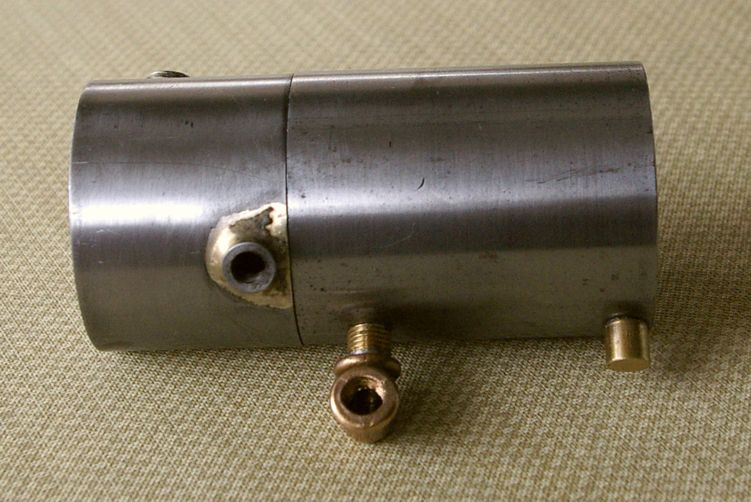
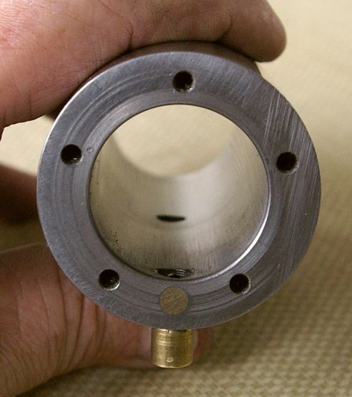
I drilled a 1/4"hole for the fuel inlet into the combustion chamber and tapped it with a #16 - 27 pipe thread. I installed a 16 -27 threaded plug into the rear hole into the cylinder, also using Loctite. I left a bit of the plug protruding in case I ever needed to get it out, knowing all too well how I tend to put things together prematurely permanently! :wall: Next I drilled the 3/16" transfer port into the cylinder wall, from the bottom of the cylinder to where it meets the newly drilled 1/4" hole into the combustion chamber. I turned a small, brass plug about .005" oversize and drove it into the bottom of the cylinder to permanently plug the end of the transfer port, then filed it flush with the bottom of the cylinder. Finally, I installed the #16 elbow and nipple into the center intake port. Here is a picture from the back of the cylinder.

_IGP2476_zps970d71c3.jpg


So, we'll see how this goes.
Chuck
 
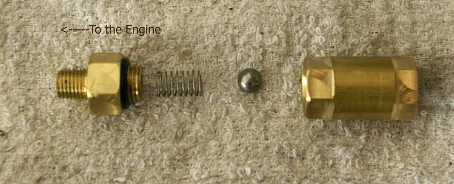
With the new, true 2 stroke setup, all the fuel mixture passages are now 3/16" diameter. This morning I made a new, larger check valve. This allows fuel from the carburetor into the transfer port, but will not allow a backflow through the carburetor when the fuel mixture is being transferred from the rear of the cylinder into the combustion chamber. This valve has a 1/4" ball.

_IGP2477_zps718d76f4.jpg


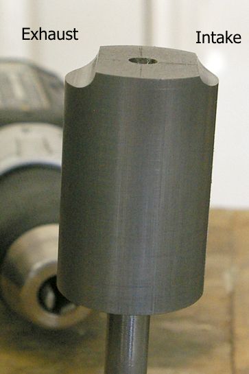
Next, I cut some new profiles in the top of the piston.

_IGP2478_zpsec60a2dd.jpg


The smaller cut side is over the intake port. The shape is designed to redirect the fuel mixture toward the top of the cylinder helping push the spent exhaust gases out the exhaust port.

And, last, but not least... here is what we've all been looking forward to!

https://www.youtube.com/watch?v=vZ2kPzEUyXc

Aahhh, success is sweet!

Chuck
 
Well done Chuck and no ring in any shape or form which proves another point.
Vince
 
Well done, Chuck. You can heave a big sigh of relief now. I know that engine has fought you right from the word go.---Brian
 
Back
Top