- Joined
- Jun 4, 2008
- Messages
- 3,294
- Reaction score
- 636
I was inspired by Bogstandard's starting to build this engine, and it looks as if it would be a good (or ambitious) step up from my first two engine builds. For those not familiar with this engine, it's a 5-cylinder radial: http://lineymachine.googlepages.com/l5
Since I still have a bit to finish on the paddleduck engine plus blinging it and Brian's beam engine, I will work on this in fits and starts as time allows. In the meantime, I still need to accumulate tooling that I don't already have.
The first bit is a very thin lathe grooving tool to cut the fins on all the cylinders. The plans are showing .025" grooves, which seems almost paper thin to me. I started by grinding the end of a 3/8" HSS blank on grinding wheel, till I had a width of around .07. The remainder of the forming was done on a manual surface grinder at school. The sides need relief, and I guessed at a 5-degree angle on each side (10 degrees included). To achieve this a sine vise was set at 5 degrees using gauge blocks, and the tool clamped in the vise with the botom side of the tool on the high side of the vise jaws. The left side of the tool must be ground first in order to support the tool with a parallel when grinding the other.
I actually ground it down to .03", but decided to stop as the bottom of the blade was so thin. I think that 5 degrees is too much; 2.5 should be better.
Here's the result:
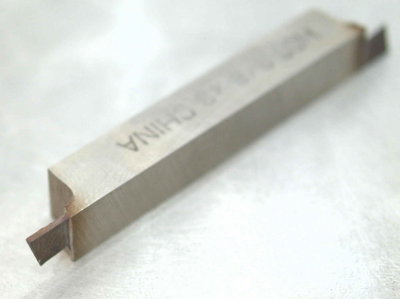
The grooves in the cylinders aren't critical dimensionally, and aren't deep. We'll see how the tool holds up.
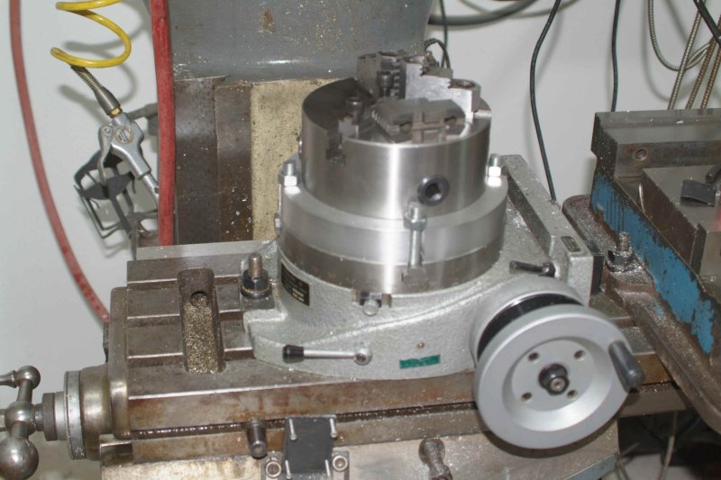
Another necessity for this build is a rotary table, and some of the parts will require that it be mounted vertically. I'd been shopping for a rotab for some time, and found the PhaseII 8" H/V on sale at Enco. Unfortunately they don't honor the free shipping on these tables, and shipping would have raised the price by $75. I called MSC, which has a local presence, and was told that they'd match the Enco price. I picked it up yesterday.
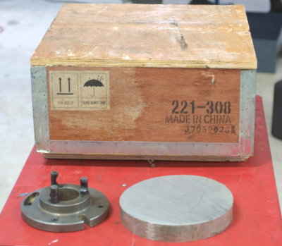
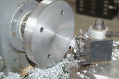
Here's the packing crate, along with a piece of 2" thick 8" diameter aluminum that will be a mounting plate for a 3-jaw chuck eventually. Alongside is a D1-3 backplate that I will use to attach the aluminum to the lathe to cleam up the faces and edges.
Inside the crate:
Once out on the workbench, the only pre-install work to do is to fill it up with spindle oil and clean the table surfaces with mineral spirits to remove the residue from the packing paper. A think coat of oil and it's ready to be mounted.
Eventually I will try to separate the vise and rotab a bit, but I didn't want to take the time to retram the vise. There is no vertical slot for the right side. Instead it must be clamped with this supplied bolt/nut/clamp combo:
There are two other similar clamps for mounting the table vertically.
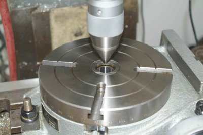
Here's the first method I decided to try to center the table under the mill spindle. I chucked a conic piece of metal that I use as a bull center on the lathe, and positioned the table so that it fit snugly all around when lowered into the center hole. Then I measured with a DTI, which showed that I was less than .005 out of dead center; good enough for me!
Since I still have a bit to finish on the paddleduck engine plus blinging it and Brian's beam engine, I will work on this in fits and starts as time allows. In the meantime, I still need to accumulate tooling that I don't already have.
The first bit is a very thin lathe grooving tool to cut the fins on all the cylinders. The plans are showing .025" grooves, which seems almost paper thin to me. I started by grinding the end of a 3/8" HSS blank on grinding wheel, till I had a width of around .07. The remainder of the forming was done on a manual surface grinder at school. The sides need relief, and I guessed at a 5-degree angle on each side (10 degrees included). To achieve this a sine vise was set at 5 degrees using gauge blocks, and the tool clamped in the vise with the botom side of the tool on the high side of the vise jaws. The left side of the tool must be ground first in order to support the tool with a parallel when grinding the other.
I actually ground it down to .03", but decided to stop as the bottom of the blade was so thin. I think that 5 degrees is too much; 2.5 should be better.
Here's the result:

The grooves in the cylinders aren't critical dimensionally, and aren't deep. We'll see how the tool holds up.
Another necessity for this build is a rotary table, and some of the parts will require that it be mounted vertically. I'd been shopping for a rotab for some time, and found the PhaseII 8" H/V on sale at Enco. Unfortunately they don't honor the free shipping on these tables, and shipping would have raised the price by $75. I called MSC, which has a local presence, and was told that they'd match the Enco price. I picked it up yesterday.
Here's the packing crate, along with a piece of 2" thick 8" diameter aluminum that will be a mounting plate for a 3-jaw chuck eventually. Alongside is a D1-3 backplate that I will use to attach the aluminum to the lathe to cleam up the faces and edges.

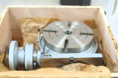
Inside the crate:

Once out on the workbench, the only pre-install work to do is to fill it up with spindle oil and clean the table surfaces with mineral spirits to remove the residue from the packing paper. A think coat of oil and it's ready to be mounted.

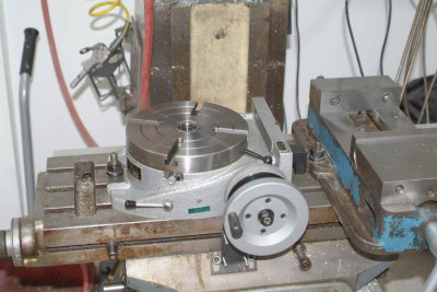
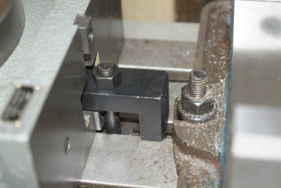
Eventually I will try to separate the vise and rotab a bit, but I didn't want to take the time to retram the vise. There is no vertical slot for the right side. Instead it must be clamped with this supplied bolt/nut/clamp combo:

There are two other similar clamps for mounting the table vertically.
Here's the first method I decided to try to center the table under the mill spindle. I chucked a conic piece of metal that I use as a bull center on the lathe, and positioned the table so that it fit snugly all around when lowered into the center hole. Then I measured with a DTI, which showed that I was less than .005 out of dead center; good enough for me!




![DreamPlan Home Design and Landscaping Software Free for Windows [PC Download]](https://m.media-amazon.com/images/I/51kvZH2dVLL._SL500_.jpg)


![Learning AutoCAD Civil 3D 2014 [Online Code]](https://m.media-amazon.com/images/I/51F3yi9fokL._SL500_.jpg)


