Kel's Poppin Double

Home Model Engine Machinist Forum

Help Support Home Model Engine Machinist Forum:

This site may earn a commission from merchant affiliate links, including eBay, Amazon, and others.
I got quite a bit done today.

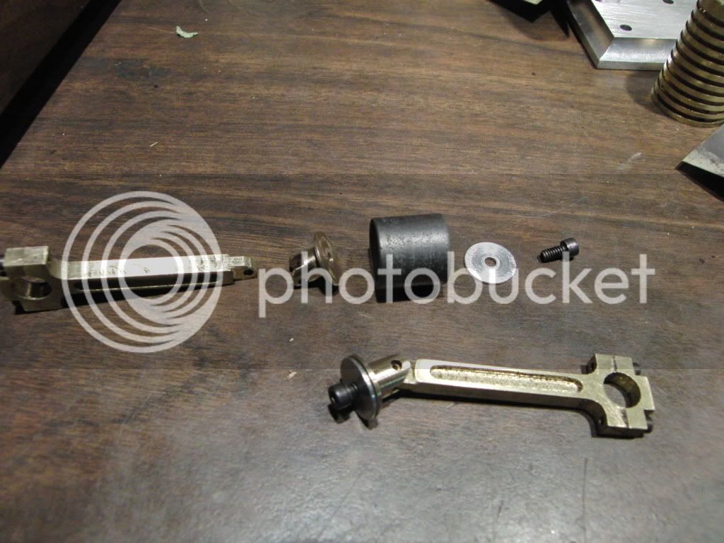
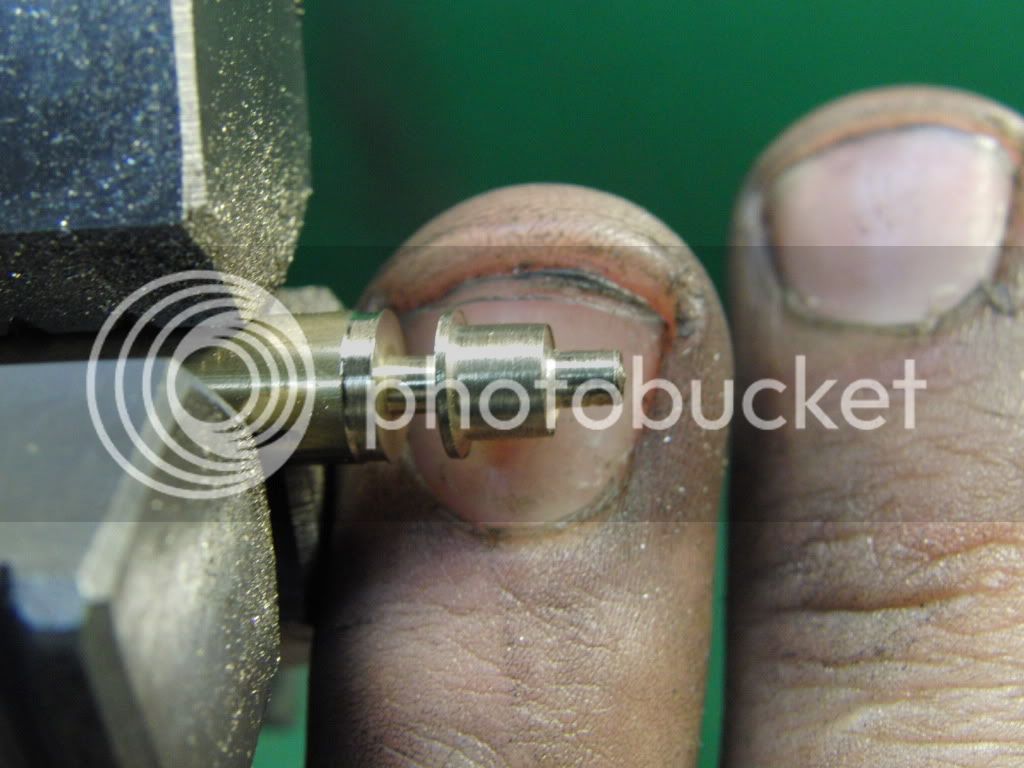
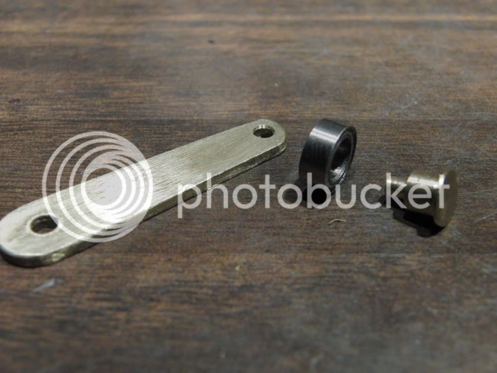
Here are the connecting rods. I came up with a more standard design, rather than the design in the plans.

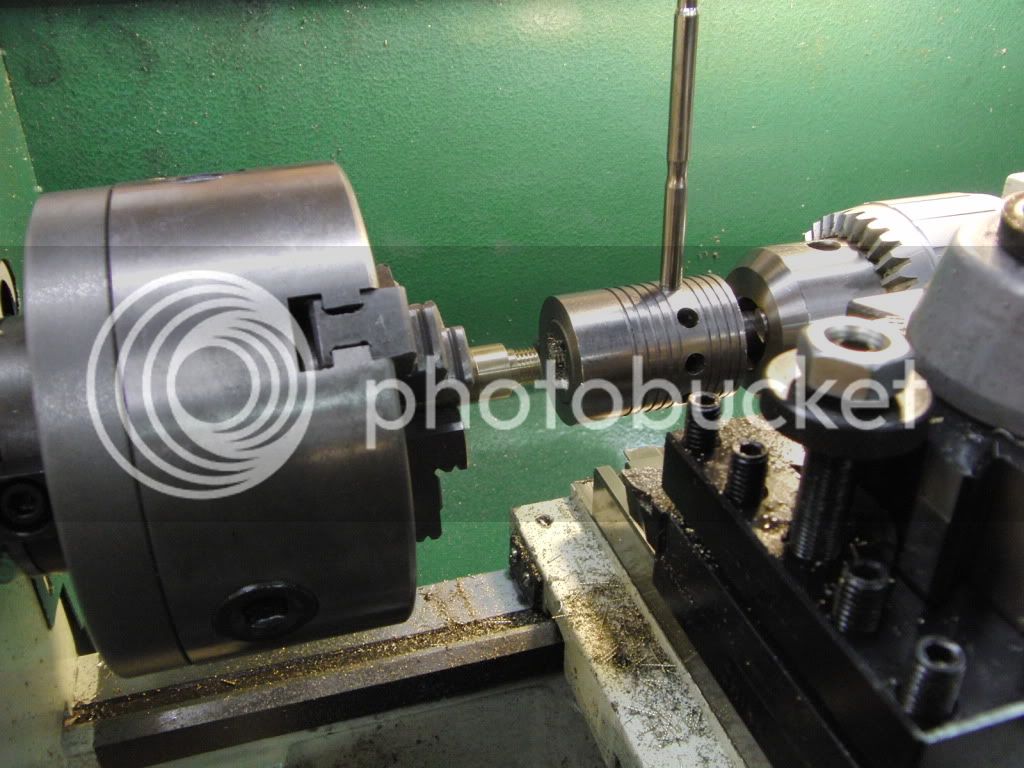
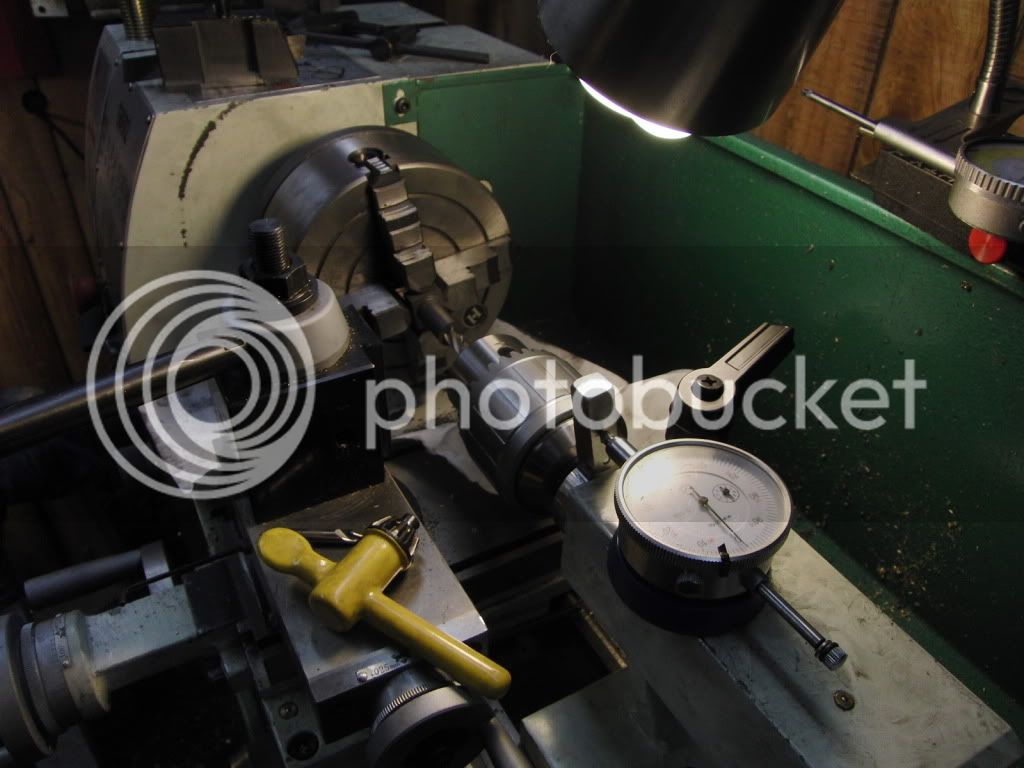
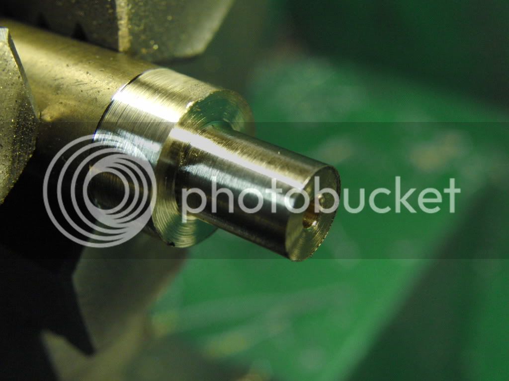
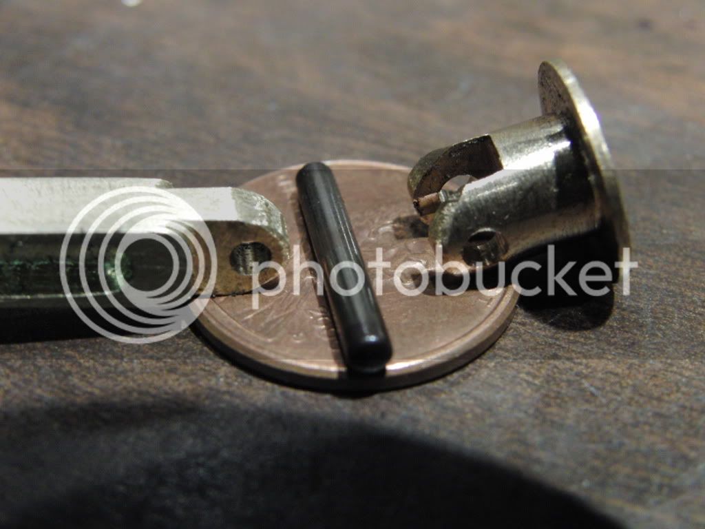
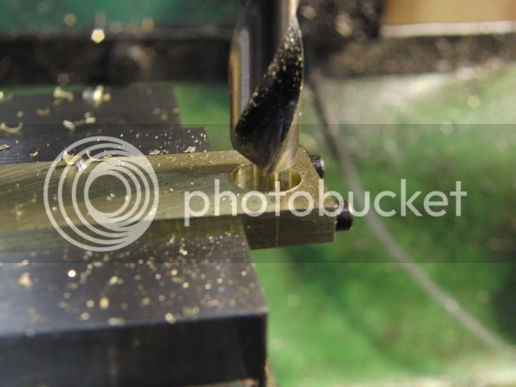
After I drilled and tapped the holes in the blank I centered it on the edge of the main bar with the cap off of it. This makes sure the center is perfectly aligned before drilling.
CIMG1027.jpg


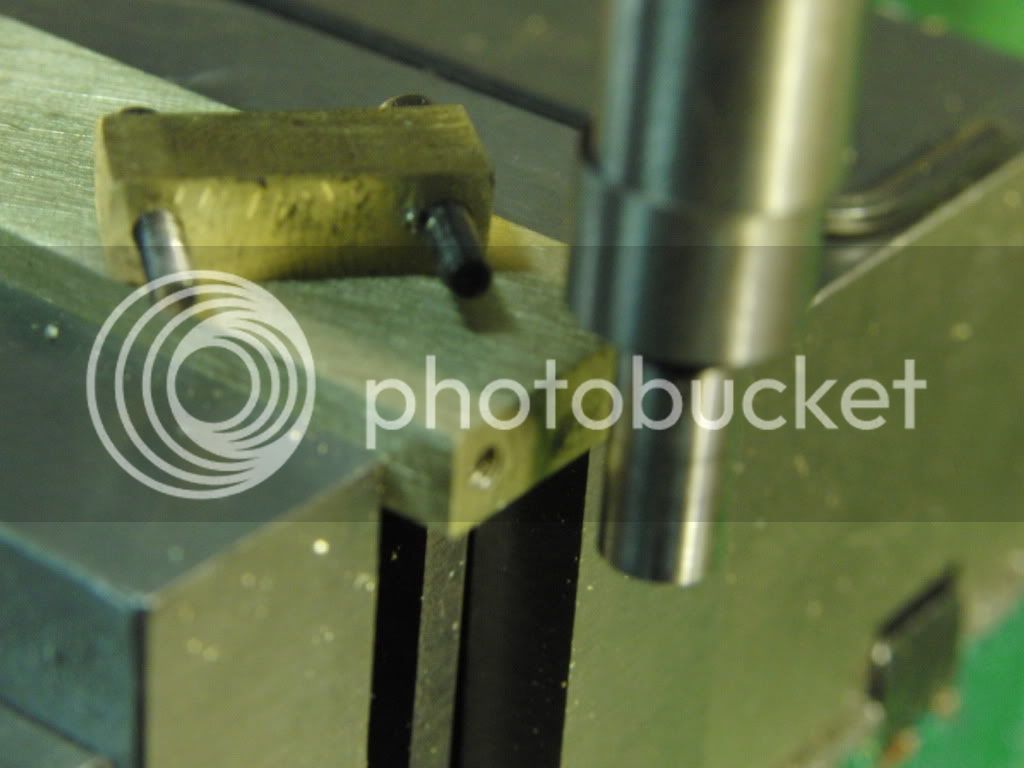
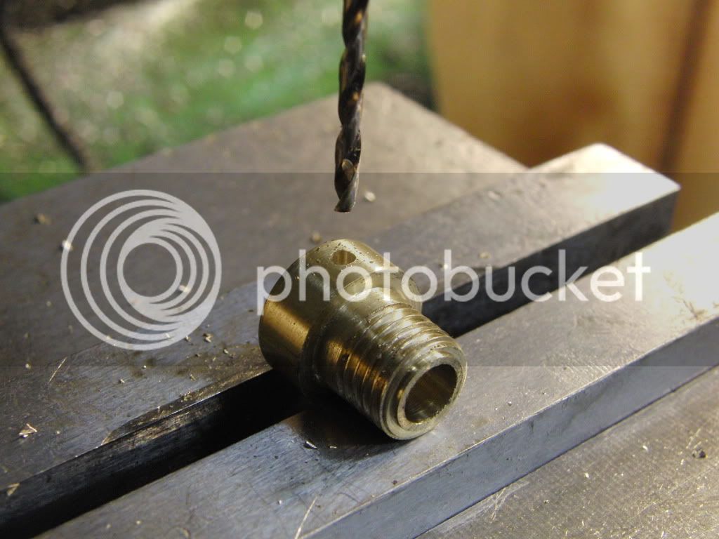
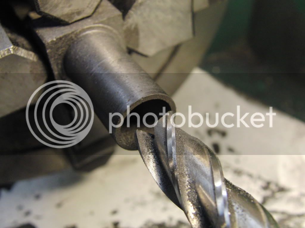
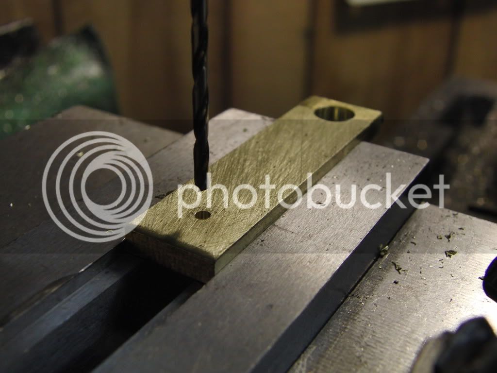
Then drilled the holes.
CIMG1030.jpg

CIMG1031.jpg

CIMG1032.jpg

CIMG1038.jpg


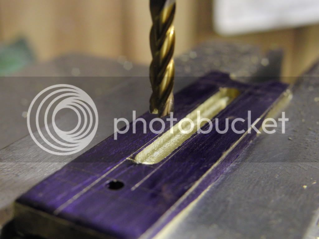
Now it is time to make the profile. I started by marking out all the lines with layout fluid. The eyeball is good enough for tis step.

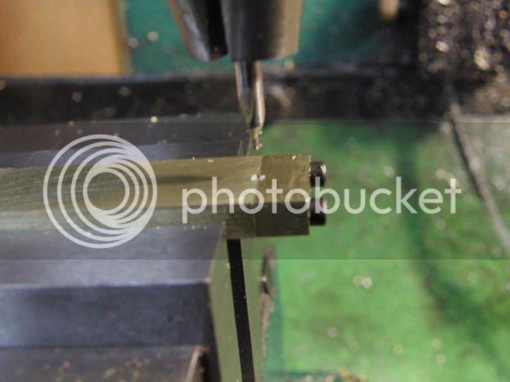
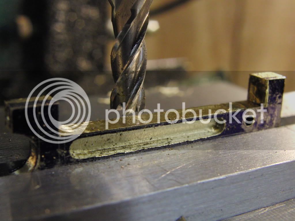
The first milling step will be to mill out the recess in the middle of the rod.
I am using a 1/8" end mill for this with a .010 depth of cut 6 times across to get it 1/16" deep.
CIMG1043.jpg


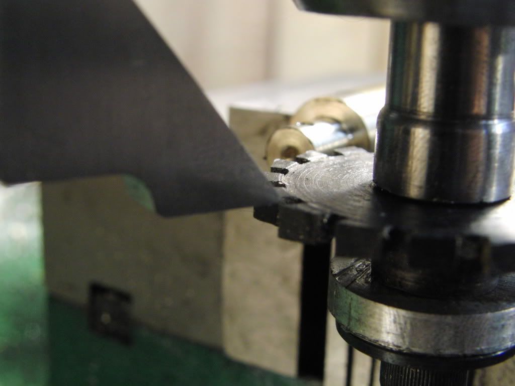
Then I proceded to mill out the sides. I am leaving a bit on the end so I can keep it parrellel in the vise when I flip it over.
CIMG1045.jpg


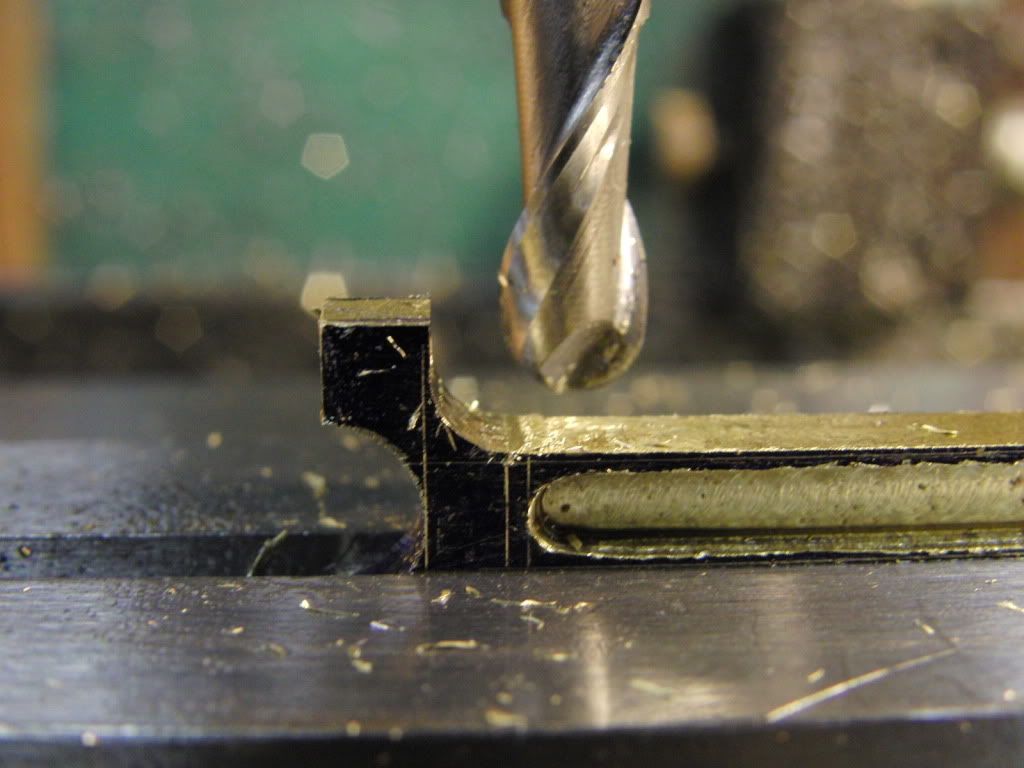
Then using a 1/4 ball end mill I made the fancy radius on the cap end.
CIMG1046.jpg

CIMG1047.jpg


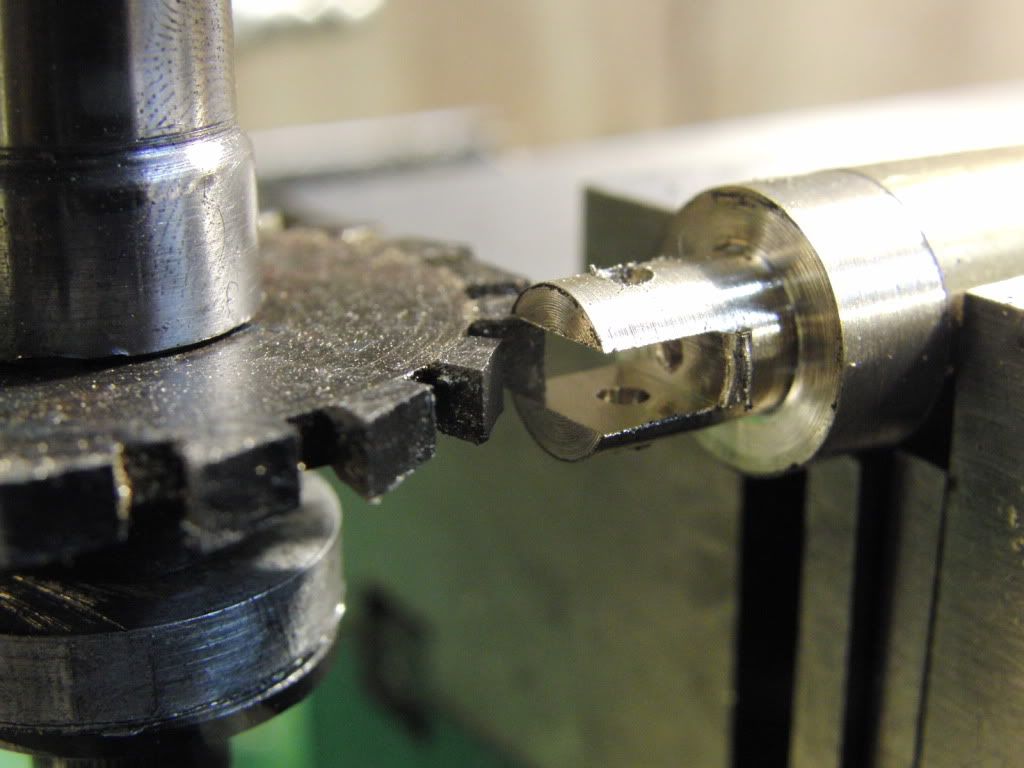
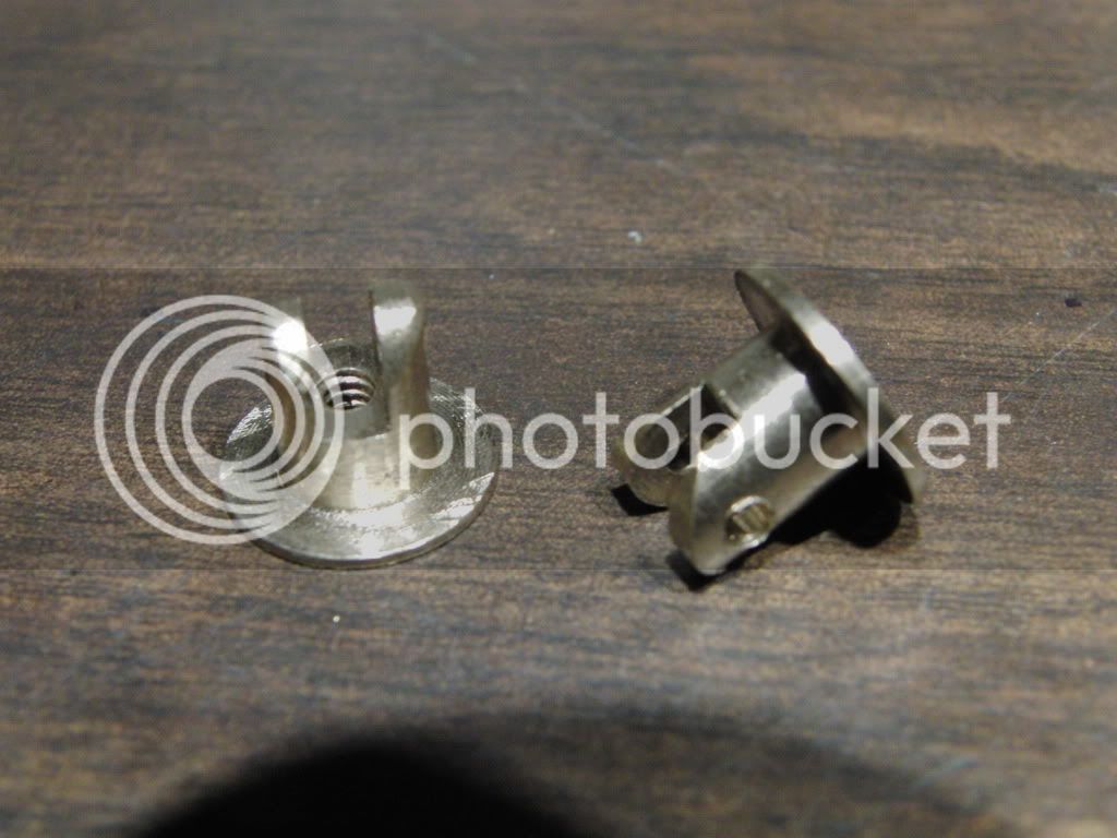
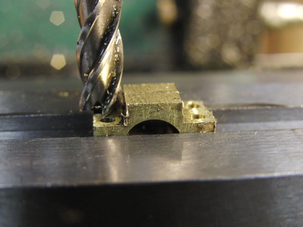
I then took the caps and milled down where the screw heads go.
CIMG1048.jpg


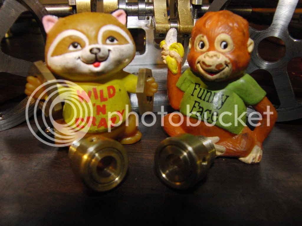
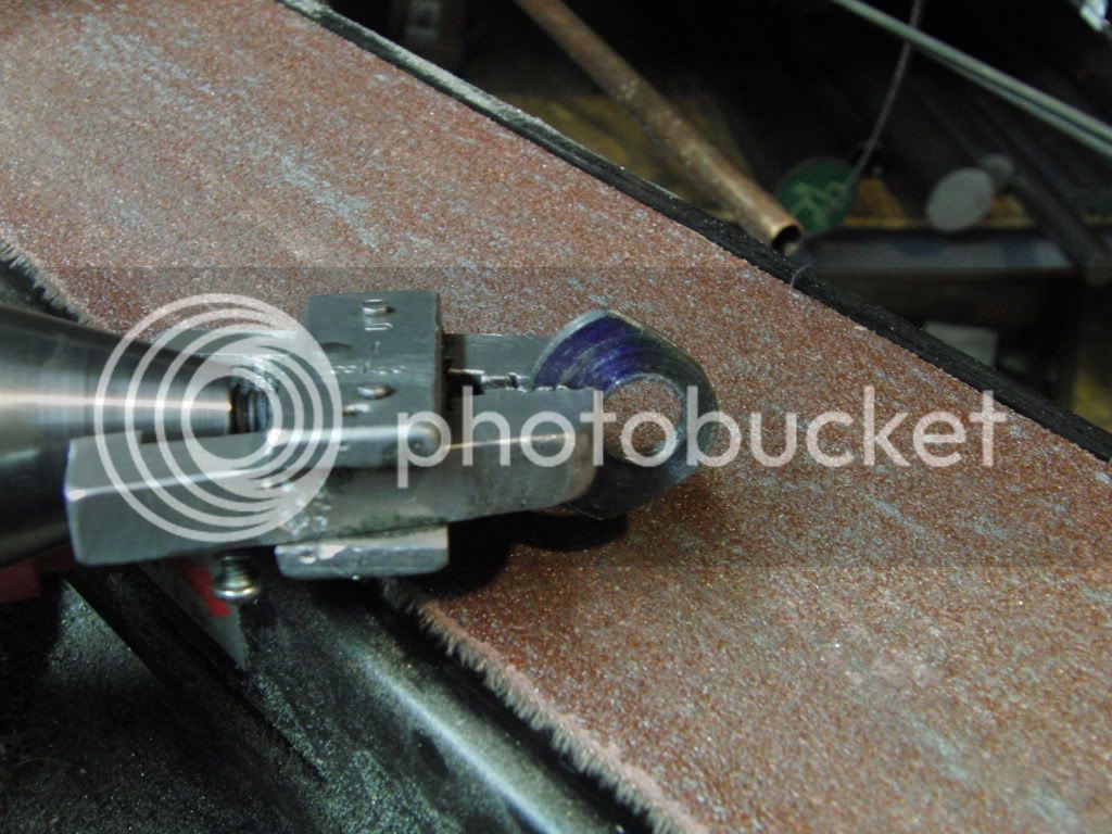
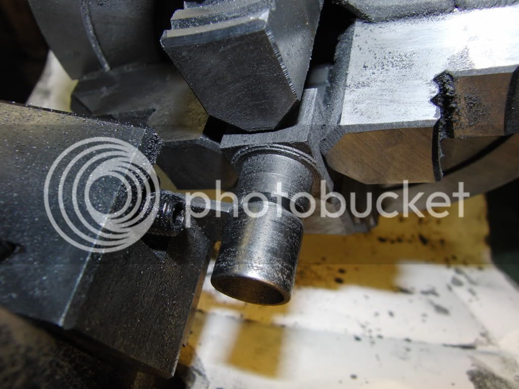
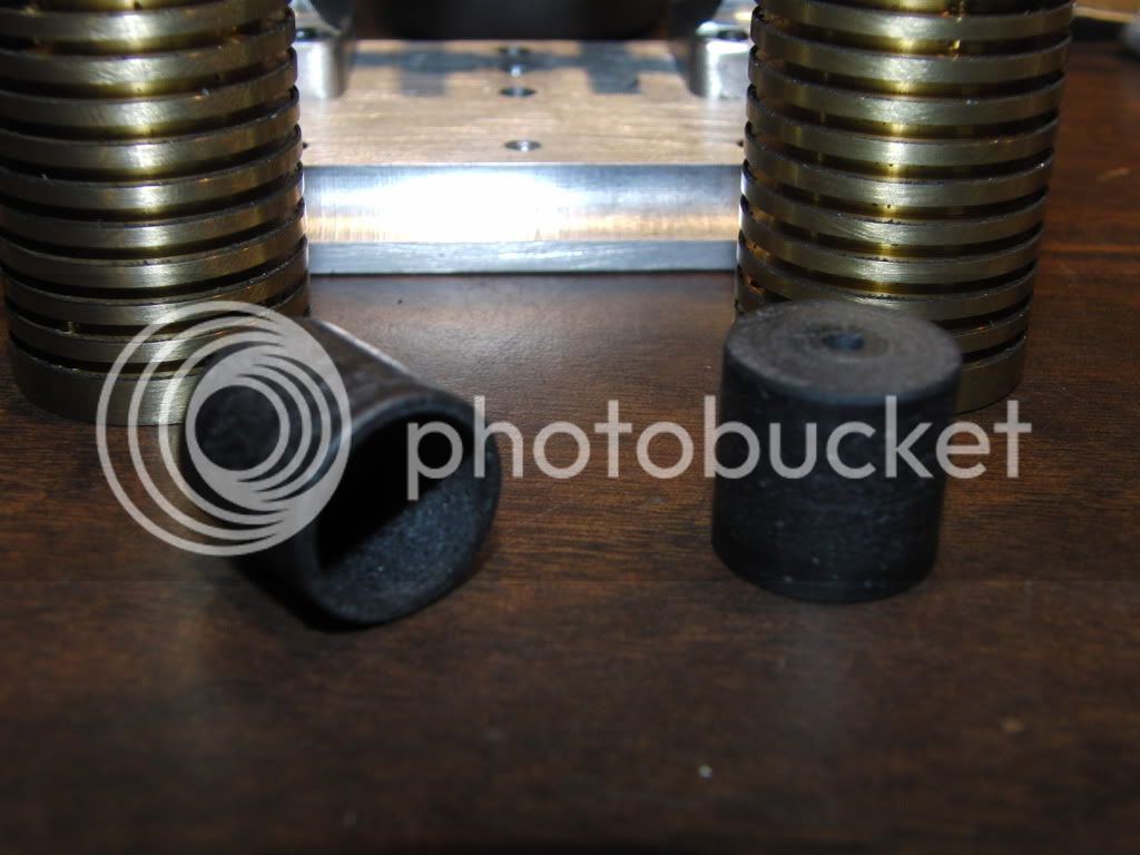
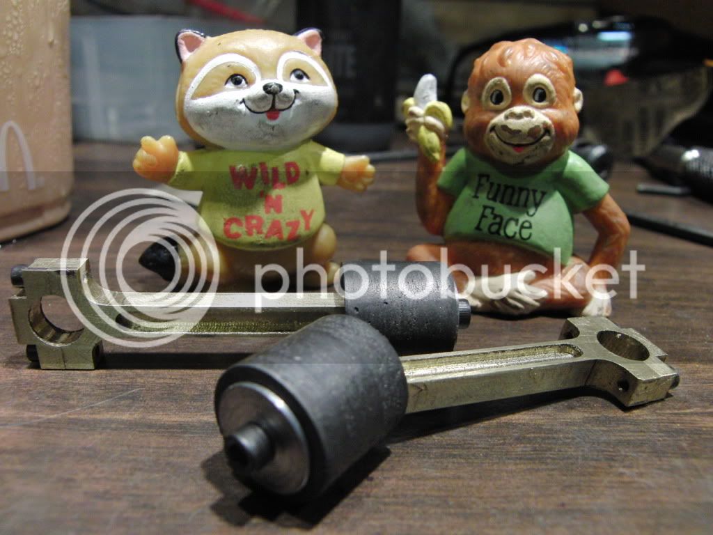
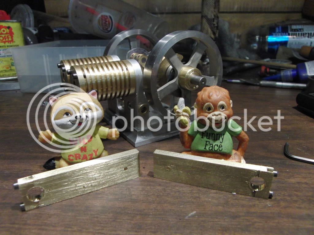
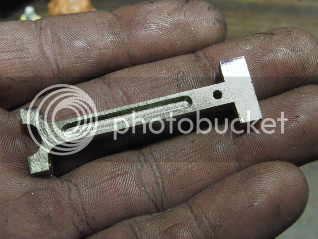
and here they are after cutting the ends off.
CIMG1051.jpg


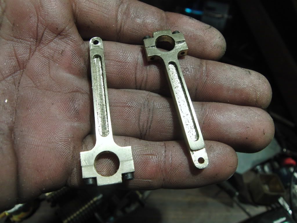
and that is how I do connecting rods.


Kel

 
Here are some pics of making the hub and hub nuts.

CIMG1003-1.jpg

CIMG1007.jpg

CIMG1004.jpg

CIMG1012.jpg


Here I am sanding the profile on the cams. Using a hand vice I made really helps holding these things tight together.
CIMG1018.jpg


Kel
 
But wait..........theres more.

I am making the piston out of graphite.

Here I am setup the cut out the inner part of the piston with an end mill. I am using a dial indicator to get it perfect.
CIMG1054.jpg


CIMG1057.jpg


and parting it off.
CIMG1058.jpg


CIMG1061.jpg


Kel
 
And Even more. I was on a roll today.

Since I am weary of the strength of graphite I made the piston thicker at the top and the yolk will have a large surface aera on it.


Here is the rough shape in the lathe,
CIMG1062.jpg


Next up, stick it in the mill and drill the hole and make the slot.

I am using a height guage to get the saw centered.
CIMG1063.jpg


and cutting the slot.
CIMG1065.jpg


after a quick trip to the sander to round off the end It was back to the lath to part it off.

and here they are
CIMG1066.jpg


here are the assemblies
CIMG1067.jpg


I am using a roller bearing from a 115 HP Yamaha Outboard for the wrist pin. It is a press fit in the rod and a loose fit on the yolk. This is so the yolk dose not crush when pressing it together.
CIMG1070.jpg


and the completed piston and rod assemblies.
CIMG1073.jpg


Kel

 
Kel,

Way to go.

Sounds good.

I'm looking forward to its completion.

SAM
 
Pretty neatly done, Kel. You sure get right to it, and have a lot finished in a day!

You can really say that your single "does something", when, as so many of us are asked
about our engines, someone says "What does it do?". It's a production break-in machine!

Isn't it odd how a graphite piston can look so rough, yet be so silky smooth? Pretty
good stuff, and stronger than it seems, considering it's feather light weight.

Thanks for the interesting update.

Dean
 
Thanks Sam and Dean.

SAM in LA said:
I'm looking forward to its completion.
SAM

Me too :big: :big:

Dean, Yes I do often get asked "What do they do? Now I have an answer. :big:

The graphite is some strange stuff, the piece I got has tiny pockets of air in it, you can see divits in the piston in the pic with the rods. It has a weird appearance but it is indeed very smooth. They slide in the cylinder with hardly any friction at all.

A side note, I got it spinning about 2500 rpm using air power and it has nearly no vibration at all, the side-by-side configuration is quite stable. There was a lot of vibration without the conrod and pistons installed. I was worried about the reciprocating masses, but I feel good about it now.

Kel

 
This is looking good Kel, all those tiny parts!
I like your flexible coupling in the run in shot, those poppins sure do get up some revs
Byrne
 
kcmillin said:
I was on a roll today.

I'll say. Gee.

The spokes look real good to me. That technique is something I want to try sometime.

Looking real good Kel. Didn't seem to take much fiddling.
 
Thanks Byrne and Zee!

Byrne, yes these poppins are great, very somewhat simple build and incredibly reliable. I have clocked my single at 1300 RPM but is mostly runs at about 1100rpm or so. Great design.

Zee, the flywheels were something I thought to be very difficult, until I tried it that is. A little thought and it comes out nice and easy, just a little time consuming. These two took me a day to make, With a few chillin' breaks here and there.

Kel
 
Well a surprise today at work, got the afternoon off, Decided to go in the basement and bust out the valve rods and arms.

I somehow lost the pics off the arm and rods, but here are are some pics of the bearing holder being made.

CIMG1088.jpg


and here is the arm assembly. The bearing gets installed by peening the small end of the holder once it has been put in the arm.

CIMG1089.jpg


all I have left to make are the springs, but I could not wait to get the thing runnin.

So... I put the thing in the vice, made the nuts for the valves and made the valves. I hooked up some crude springs to open the valves during operation.


This is by no means a finished engine, I just wanted to see if it would run.

http://www.youtube.com/v/B-J-6xyql94&hl=en


I clocked it at 1450 rpm before things started to come loose and it resulted in bent valves. So I have to make some more of those, its good to have spares, and they are incredibly easy to make.

She was runnin for about 30 minutes all together, It did not get as hot as my single poppin. Does brass take away heat better than steel?

Still a lot more to do.

Make the springs.

Make the base.

and maybe a throttle of some sort. Not sure yet.

Kel
 
Wellll it just goes and goes, dudinit!
Darn good runner already, Kel. Moving one of the burners away gives you a very effective
throttle for it, too.

I know the springs aren't the final item, but they do give some additional visual interest,
flopping around down there like a couple of hooked trout. I think the whole shebang
is just better than pie!

Dean
 
Kel,

Good job.

Looks like it is a good and smooth runner.

SAM
 
Great work, and it runs really well Kel! How can these things be throttled back, apart from moving the flame a little? ???

Vic.
 
Runs great, Kel. Nice work. Makes me want to go back to work on some of my flamelicker attempts that never worked right.

Chuck
 
Thanks!! Dean, Zee, Sam, Bogs, Vic, and Chuck. I really appreciate all your kind words.

This is an incredible design for a flame eater engine. My praises go to its designer. Whoever that may be. (I'm not sure who it was, I find a few different names and cannot come up with a conclusion)

I would recommend it to anyone. I love to just let her run whenever I'm in the shop. A motivational speaker of sorts.

Finish that part Kel, Quack Quack Quack

Measure twice Kel, Quack Quack Quack

dont screw up Kel, Quack Quack Quack


I have fun ;D


Vic, These poppins can be timed through a wide range of advance with the cam. . It will run anywhere from near 0 degrees, up to about 70 degrees Before bottom dead center.

If I have her around 50 to 60 degrees she really hums, the single generally runs about 1100 - 1200 rpm range. The double so far has topped out near 1700 RPM but stays steady at 1400.

If I time it to around zero it will run about 250-350 RPM

only bad part is I have not found a way to do this while the engine is running. That would be pretty cool. If only there was a way.

Other than timing and flame position I have thought about a "Drag Throttle"
This would work by friction, I could put a string or something and wrap it halfway around the center of the crank. If I apply pressure to this it will slow the engine down, Just like taking your finger and rubbing it against the flywheel very lightly to slow the engine.


I still need to dry out the "Sand" in my sandblasting cabinet to finish the parts. Not sure how I am going to do this yet. Or if I should just replace it. I can almost make a sand castle with it.

I really like the look of sandblasted metal, almost casting like.

Thanks again guys!

Kel
 
kel,

Apologies for my tardy response, this morning was the 1st time, (for a couple of days), that I was able to view the video. :eek:

Your engine is as sweet as a virgin's breath. :bow: :bow:

Best Regards
Bob
 
Back
Top