Kel's Poppin Double

Home Model Engine Machinist Forum

Help Support Home Model Engine Machinist Forum:

This site may earn a commission from merchant affiliate links, including eBay, Amazon, and others.

kcmillin

Project of the Month Winner!!!
Project of the Month Winner
Joined
Jan 19, 2010
Messages
1,193
Reaction score
41
I liked the poppin so much I wanted to build another one.

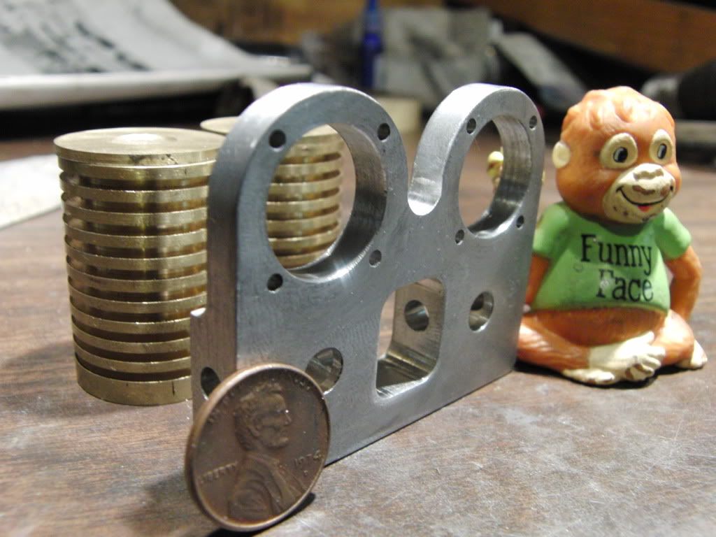
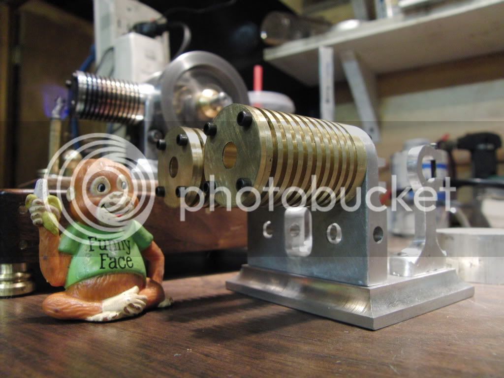
But I thought, lets do it a little different. How about two brass cylinders. Oooh, a double brass poppin, thats what Ill do. ;D


I actually started making the cylinders a couple weeks ago, right before I got my new lathe, so I was a little pre occupied and could not get pics up til now.

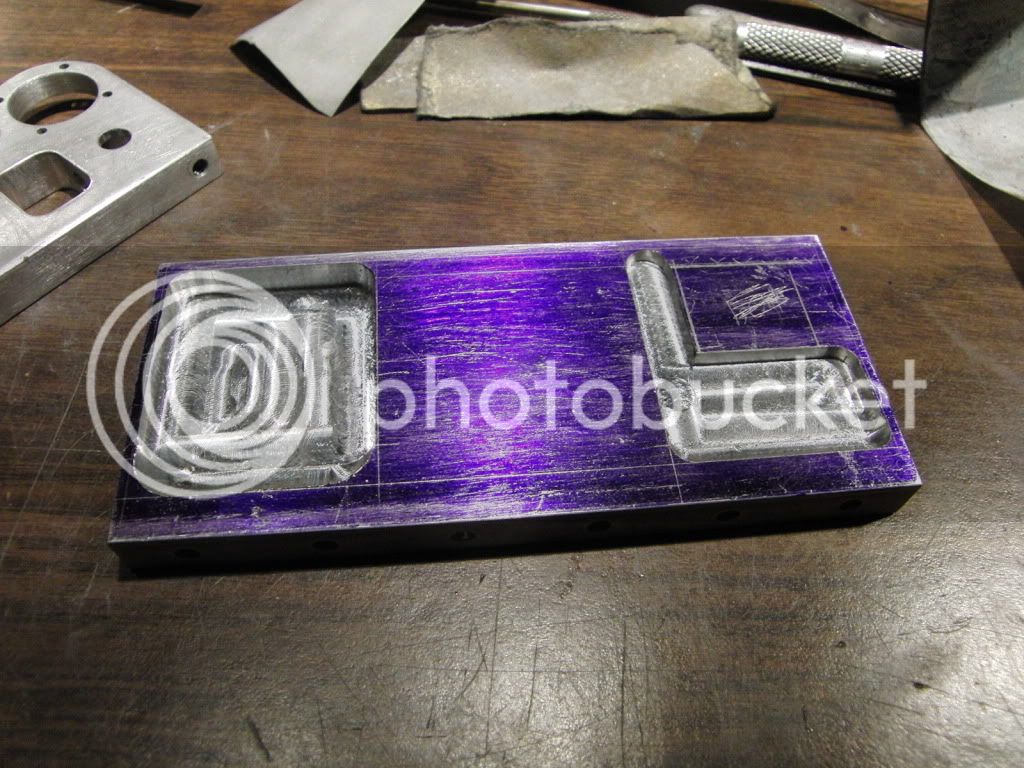
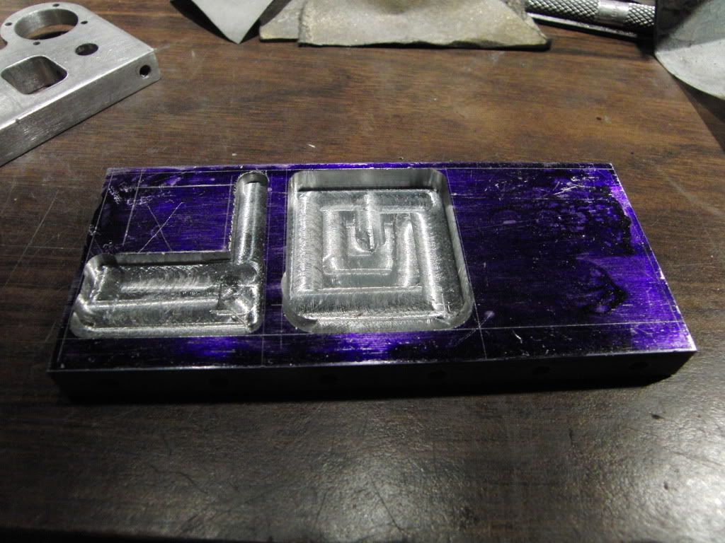
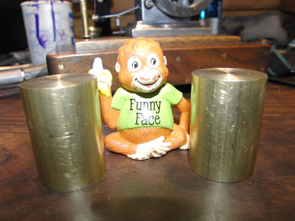
Here is what I started with.
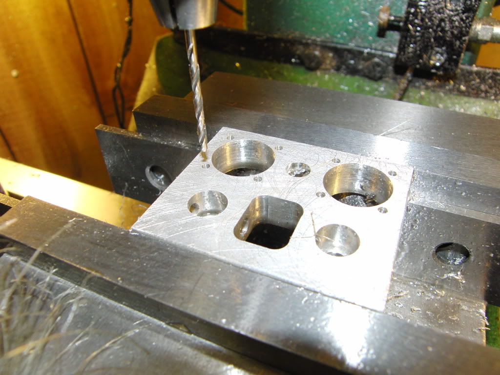
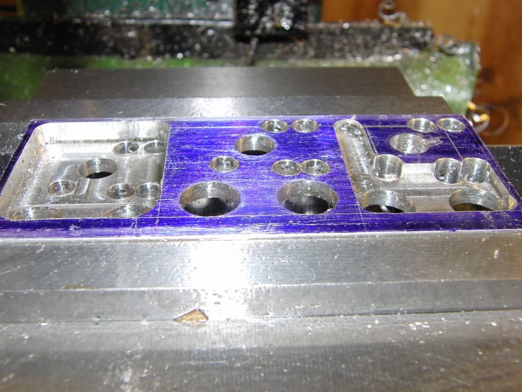
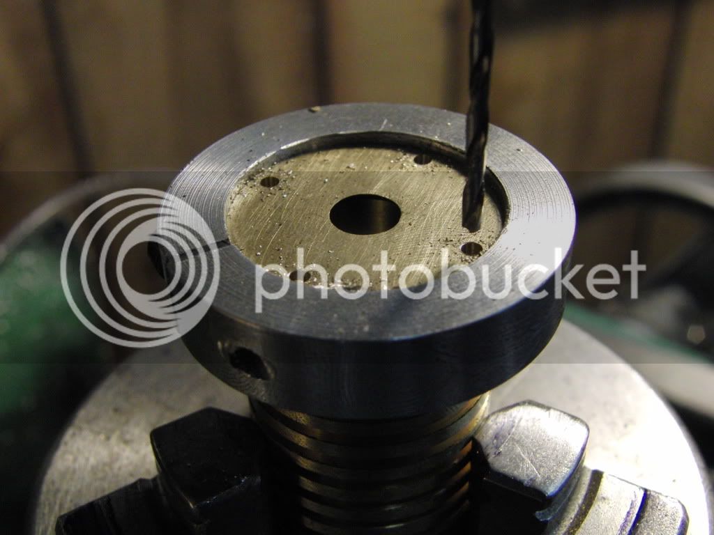
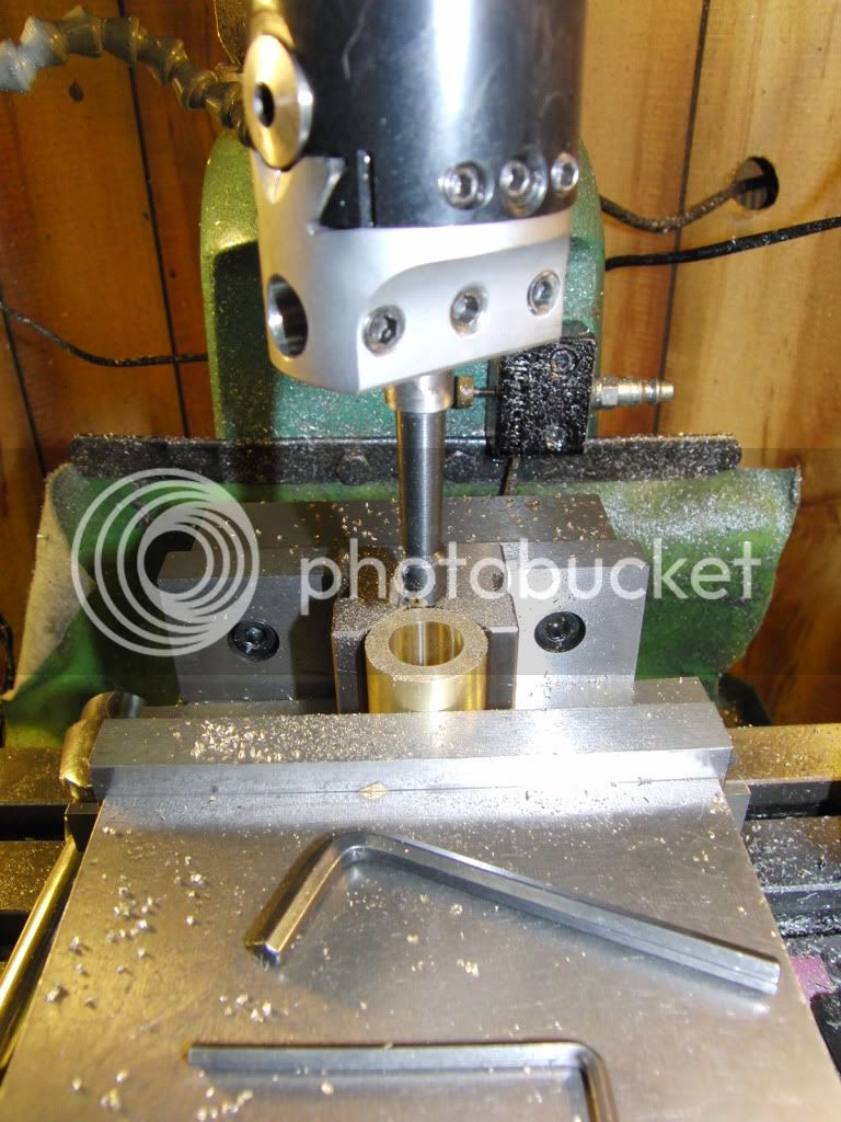
CIMG0796.jpg


Drilling the hole,
CIMG0797.jpg


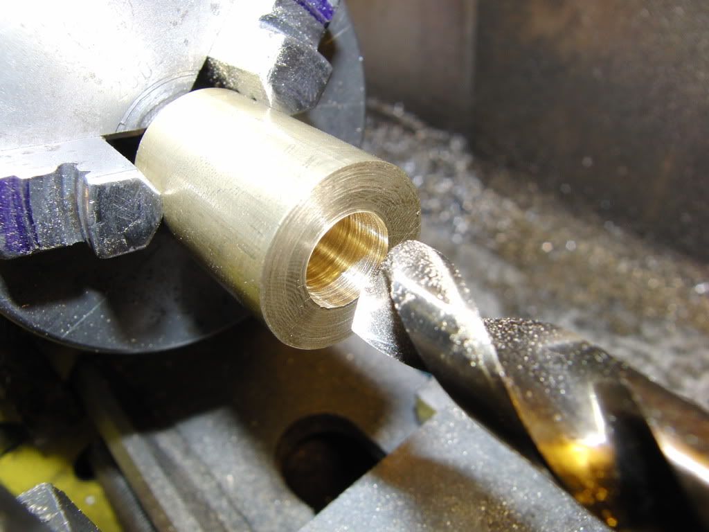
Boring the hole, (This is all standard stuff here, nothing exciting)
CIMG0799.jpg


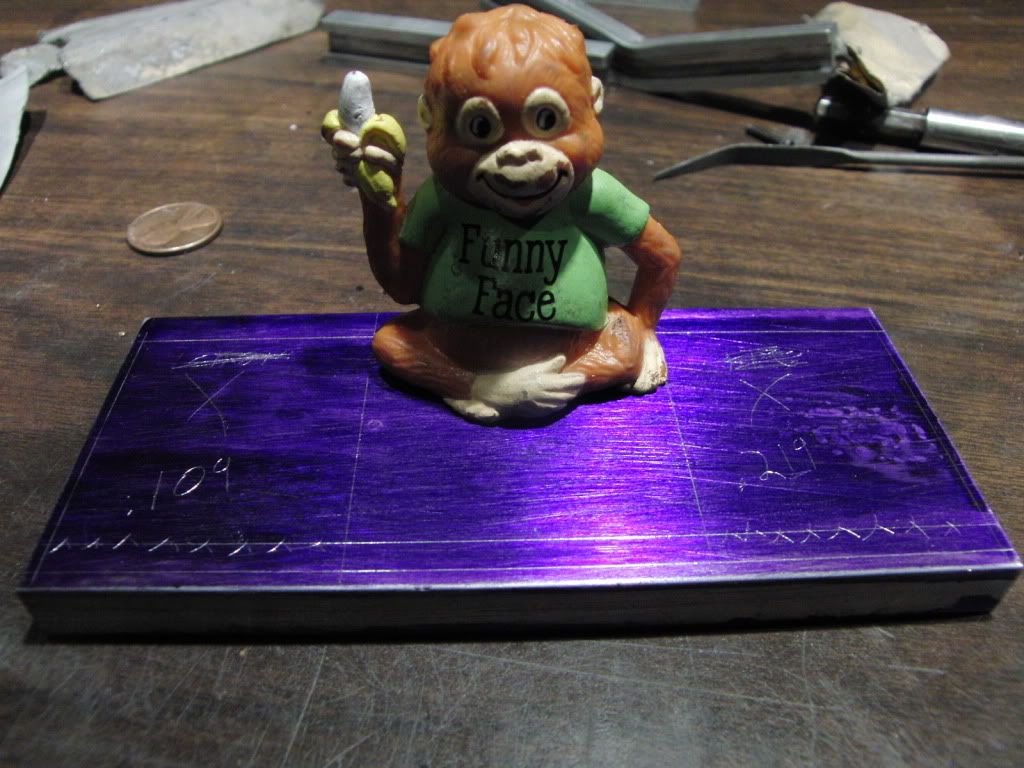
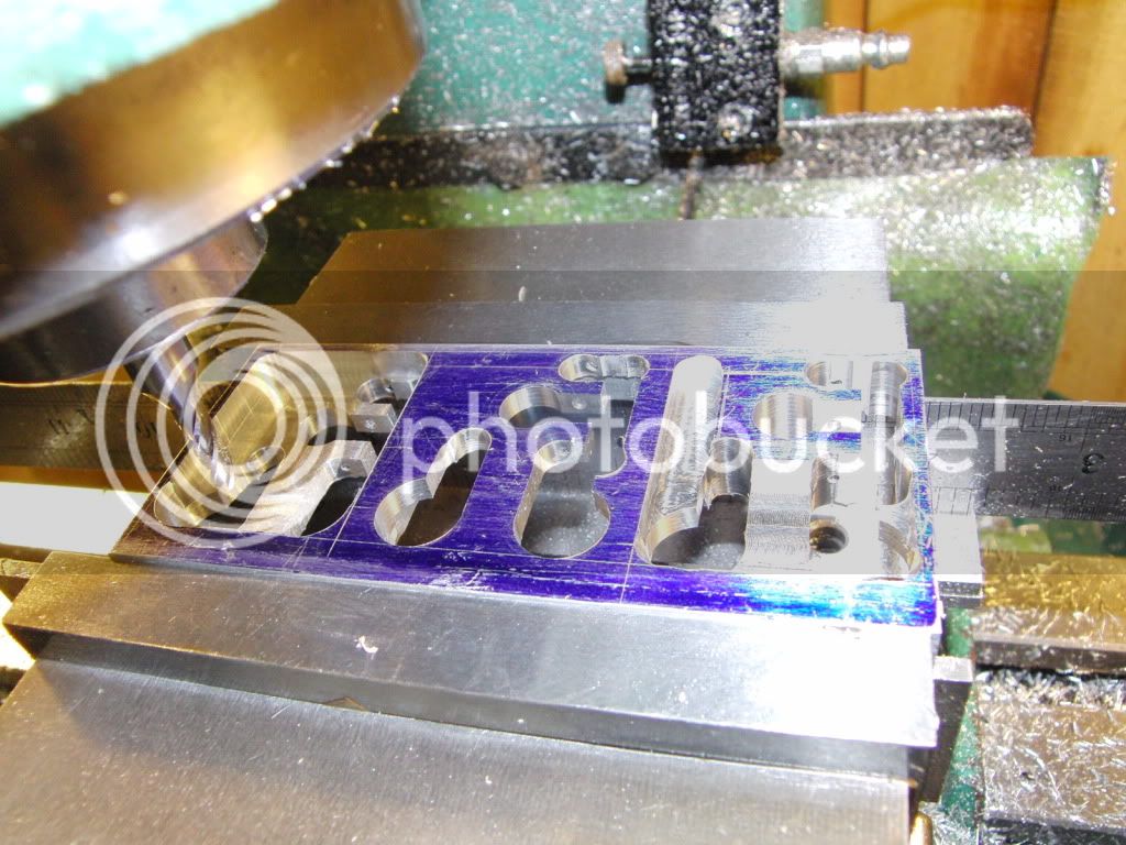
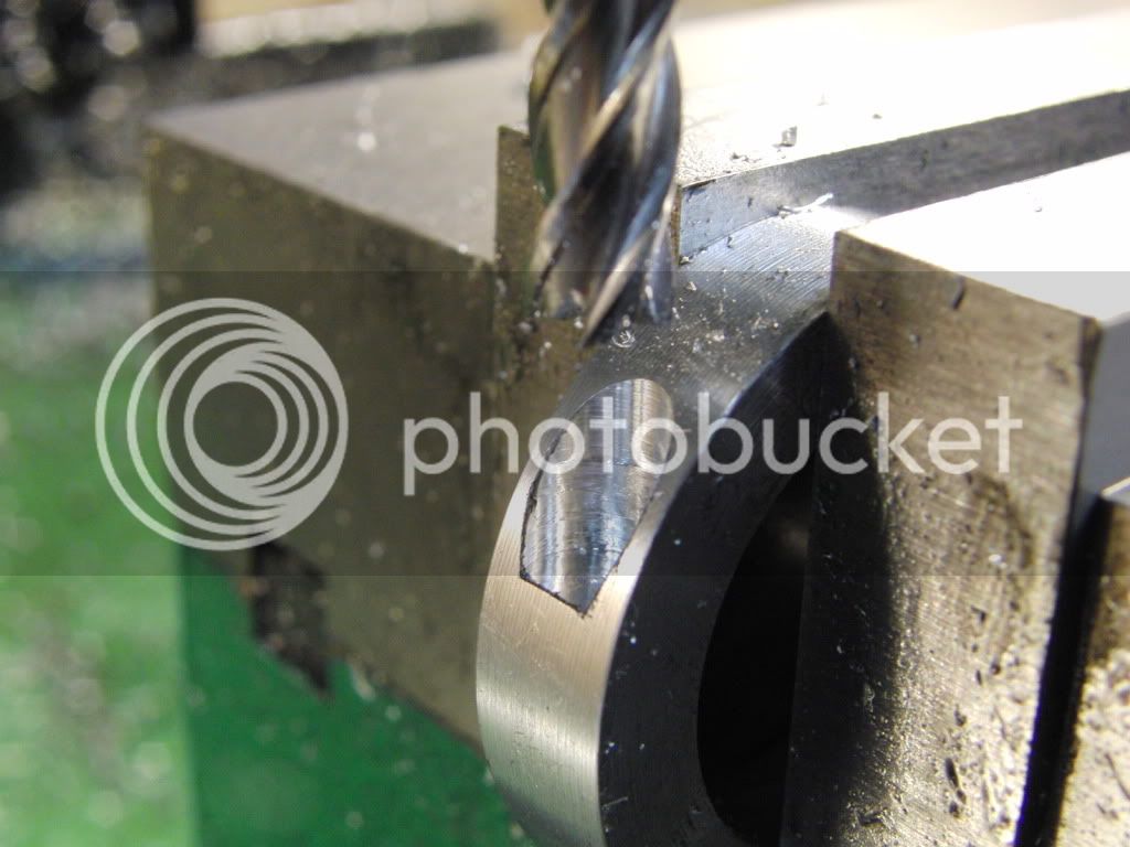
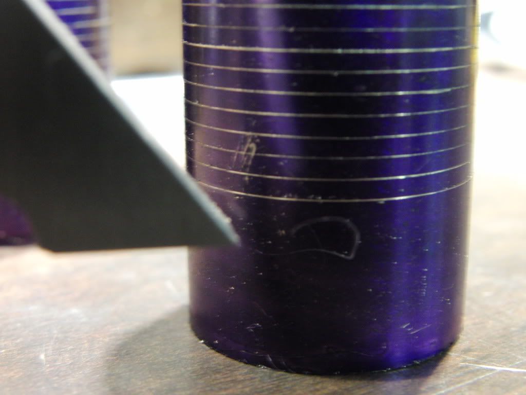
Marking out the fins with my height guage.
CIMG0801.jpg


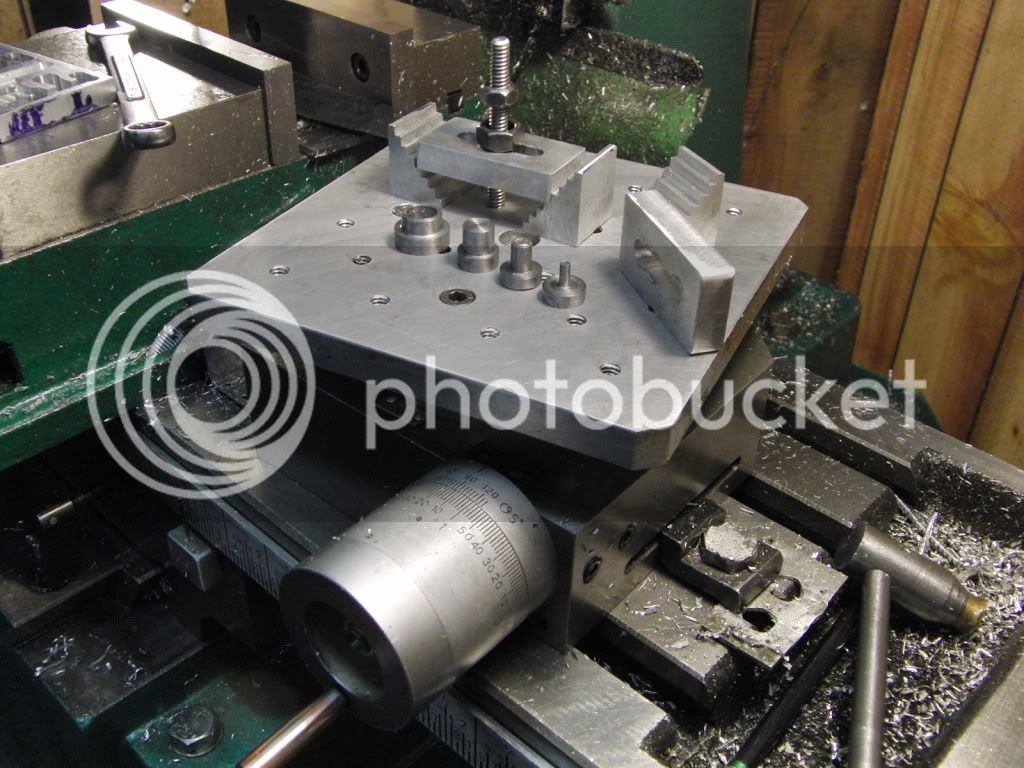
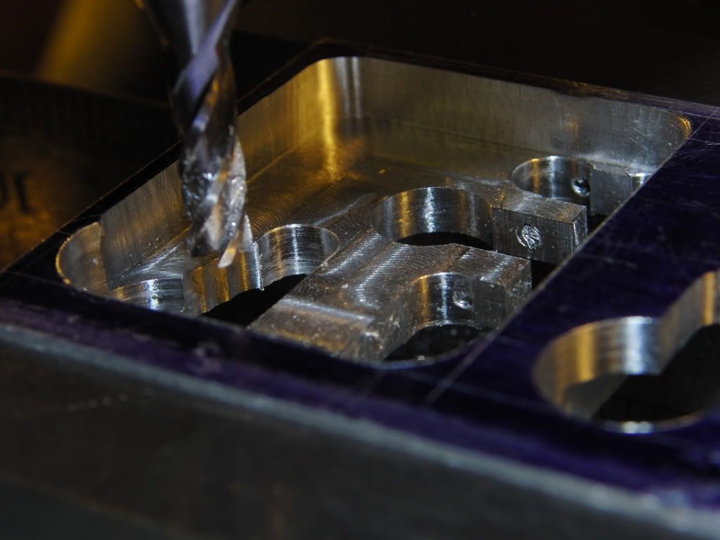
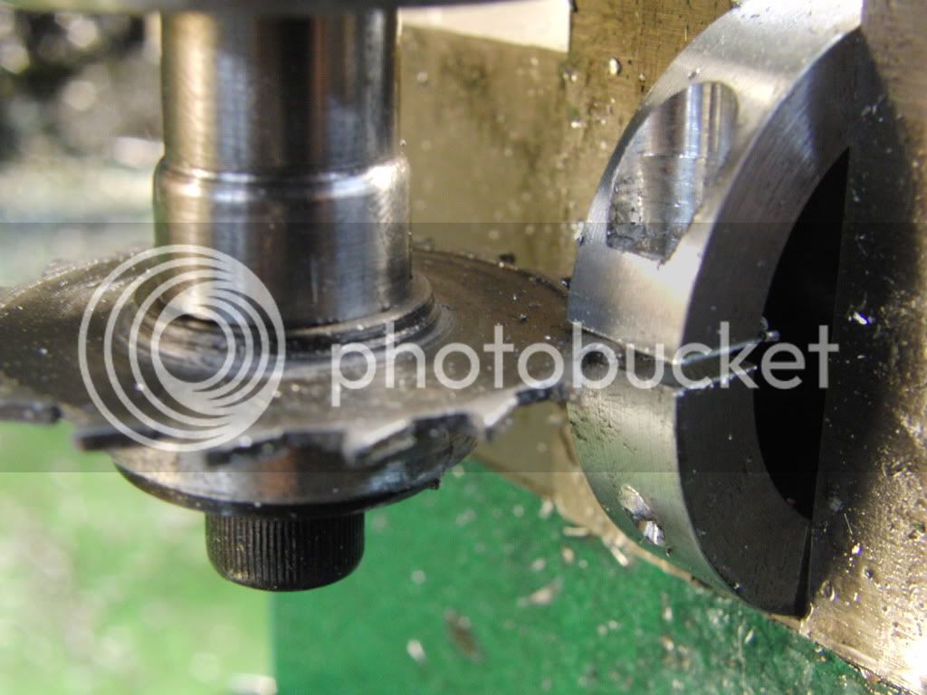
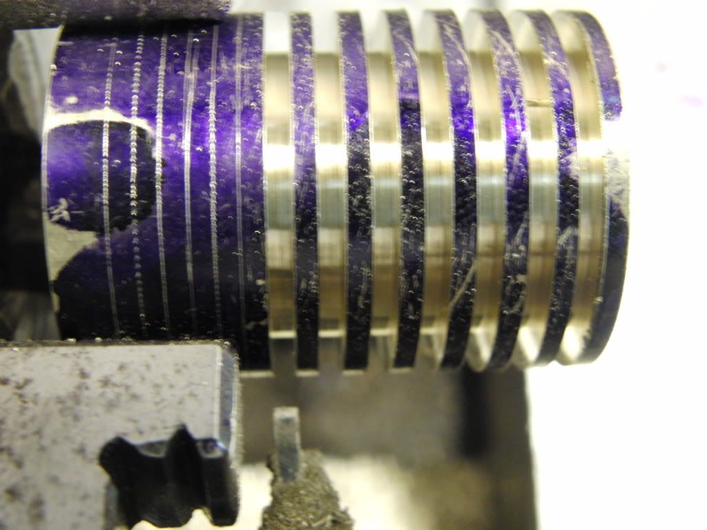
Now, cutting the fins, Brass cuts like a champ, I am always nervous when I use a parting blade, but It seems like with brass you can ram the tool in and all is well.
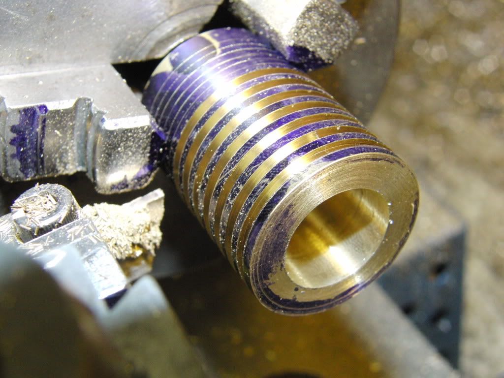
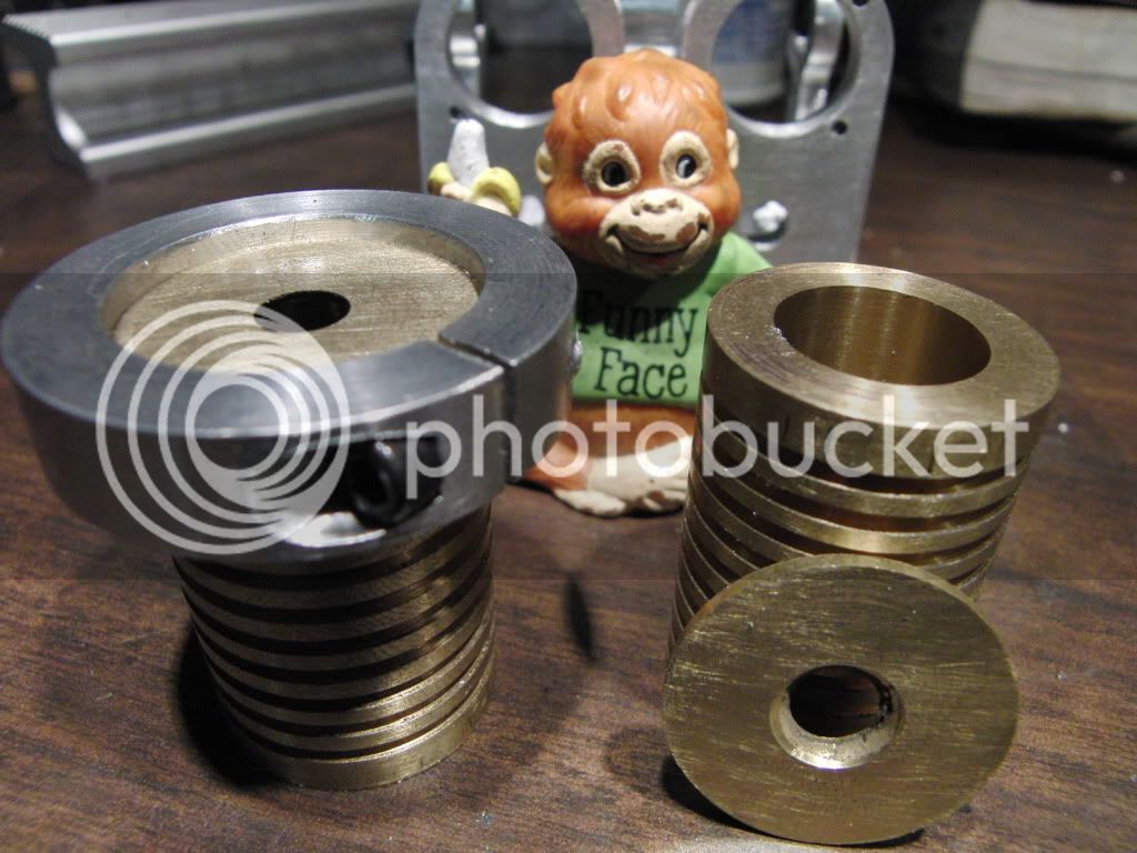
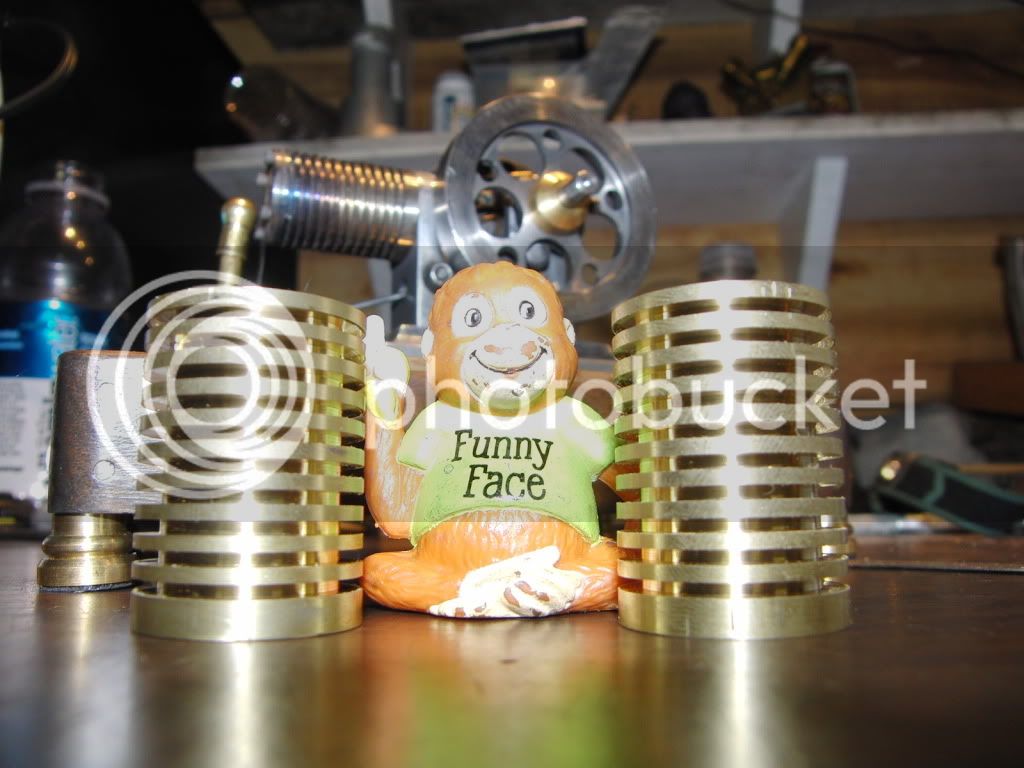
CIMG0802.jpg

CIMG0803.jpg


Here they are.
CIMG0809.jpg


Kel
 
Last night I got started work on the "Standard"

It will be made in 5 pieces. Front, Bottom, and the three bearing holders.

I started with the front of it.

Here I am drilling all the required holes.
CIMG0856.jpg


And now the fun part. I see alot of great work on the rotary table and want to join the fun. I seen in one of Deans post a great tooling table and aluminum clamps and all. So I made a table top for my R/T and I am very pleased with it.

Here I am cutting the profile of the cylinders on top of the front of the standard.
CIMG0858.jpg

CIMG0859.jpg

CIMG0860.jpg


I love the rotary table.

Here is the finished (Almost, needs powdercoat) front standard.

CIMG0871.jpg


I am very happy with the result, and cant wait to get the rest done.

Next up, the bearing supports.

Kel
 
Nice work Kel, some impressive milling on there. What size Rotary Table do you use?

Vic.
 
Nice project, Kel. Should be a real nice looking engine!

Chuck
 
Thanks Vic and Chuck.

Vic, I have a 4 inch R/T with a 6 inch square tooling plate mounted on it. (This is the first time I used the plate)

Here is a pic.
CIMG0890.jpg


Kel
 
I got the Bearing Supports milled up this morning. I have seen a method of making parts that I always wanted to try.

I started with a 2" x 4 1/2" block of aluminum. I am going to make three slightly different parts. A left, a center and a right.

I began to mill out the recesses needed to get the correct profile on each support. (you will see why later)
CIMG0874.jpg

CIMG0876.jpg

CIMG0877.jpg


From there I drilled the 24 holes required to get the shape I needed.
CIMG0878.jpg

Now its time to start playing connect the dots with a 3/16" end mill.
CIMG0879.jpg

CIMG0880.jpg


Whilst millin' the parts out I was very pleased to see the part "Forming" right before my eyes.

Here is what I had done in the vise.
CIMG0886.jpg


Now its time to get the radius on the rear of the bearing supports.

This was even more fun. I got to use to R/T and tooling plate again.
CIMG0892.jpg

CIMG0895.jpg


Here she is, fresh off the R/T.
CIMG0899.jpg


After that, I just cut out the parts with a band saw.
CIMG0908.jpg


Here you can see how the profile is different on each part.
CIMG0910.jpg


Here they are mocked up with the front part standard thingy.
CIMG0907.jpg


Thats it for now.

Kel
 
Thanks for the pic of the RT and tooling plate Kel. It's something I need to get at some point but not sure what size and make to get. Some nice milling work again, I wouldn't know where to start doing something like that!

Vic.


Very nice Kel, If I walked away it would take me a week to find my spot again. :big: :big:

Ron
 
Kel,

It is good to see people doing experimentation with little engines, and you are doing a great job of it.

It will also allow you to see the effects as well, I played about with crank positions in relationship to each other when I made mine, and got some weird results, but found that the twin does really need to be 180 degs apart. Also, with yours being end induction you shouldn't have too much trouble controlling the flames.

I can't wait to see the end results.

Bogs
 
This is coming out neat, Kel! Nice work with the RT, and the cylinders also look great.
You sure move along! (Your pictures look much nicer, too.)

Dean
 
Kel,

Lookin' good!

I like how you milled those parts.

Clever one you are.

SAM
 
Thanks Vic, Ron, Bogs, Dean, Sam, and Zee.

Ron, I had all the x and y coordinace written down on a piece of paper so I would not loose my place. Once all 24 holes were drilled it was all freehand from there.

Bogs, yes I like seeing mods to these little engines as well. Before I found HMEM I was lurking on You Tube and watched your videos. That was a big factor in my undertaking of my first Jan Ridders flame eater. (Thanks For That) After I built my first poppin I made a V-twin based on the same bore and stroke of the poppin. The cylinders were 45 degrees apart and seemed to have allot of power, and would rev to 1400 RPM. I hope this design at 180 separation will have just as much, if not more power. (Well See)

Dean, I am very happy to have a decent camera to show my work. I hope it makes my posts more enjoyable too.

Zee, It wasn't bad until my Y axis cheap DRO reset on me. I had to re-find the edge and hopefully none of the holes were off. It turned out OK though.

Kel

PS, I cant seem to find the right spelling for co-ordinence? It seems so simple, but the spell check does not find the right word, and Google aint very helpful either. Does it even have a hyphen?
 
Ahhhhhh, thats it. Thanks Sam.

Spelling was never my strong suit. :D

Kel
 
Got some more work done on the double today.

I am making the base out of 3/8" aluminum. After drilling all the required holes and tapping the two mounting screws I wanted to spruce it up a bit.

I used a 1/2" ball end mill to make scalloped edges.
CIMG0911.jpg

CIMG0913.jpg


Here is the almost completed base (standard)
CIMG0915.jpg


Now, I put off drilling the holes into the cylinders long enough. I came up with an idea to minimize the setup time to drill 24 holes.

I centered the R/T to the mill and set the y axis offset to .422.

I wanted to drill through the cap and into the cylinder in one setup. So I had to make a clamp to hold them together.

I started with a 1 1/2 " round aluminum with a 1 inch hole through the middle.

I used an end mill to create a flat spot. and then drilled through the required hole size.
CIMG0919.jpg


Then I used a slitting saw I made out of CRS about a year ago, to make a slot.
CIMG0920.jpg


I have used this saw many times on aluminum and brass without any trouble.
Not bad for CRS

Here is the finished clamp installed on the cylinder keeping the cap in place.
CIMG0921.jpg


CIMG0922.jpg


And everything all together.
CIMG0924.jpg


Until next time............

Kel
 
Looks very impressive as an assembled unit, Kel. Good work!

Dean
 
It's looking great Kel.

You MADE the slitting saw? Wow. Got any info on that?
 
Thanks Dean and Zee.

Zee, I made the slitting saw from a 1 1/2" round CRS bar. I mounted it on a mandrel in the lathe and turned it down to the final thickness. Then about a tenth inch in I recessed the sides to create clearance. You can see that in the picture.

Then I took the whole works, Mandrel and all, and mounted it on the R/T. From there I proceded to cut teeth like portrusions on the blank with an end mill. (I did not use any fancy angles, just what looked good) After I was done, I filed the cutting edges down to a sharp point. It works like a champ for cutting aluminum, brass and wood. (I used the mandrel I made to mount it in the mill also)


Hope this wasn't to vauge of an answer, I just kinda eyballed the whole thing.


Kel
 
Back
Top