Hot Bulb Engine, here we go...

Home Model Engine Machinist Forum

Help Support Home Model Engine Machinist Forum:

This site may earn a commission from merchant affiliate links, including eBay, Amazon, and others.
cfellows said:
Shred, to your point of generous unswept cylinder volume, I've noticed this and wonder how they manage to get the compression ratio high enough to generate additional heat.

Chuck
I'm not so sure they do generate much additional heat from compression anymore. I think ignition more or less happens when the fuel-air mixture in the bulb gets lean enough to burn. That burn heats the hot-bulb for the next cycle. Were I to try building one, I think I'd start with the always-on blowlamp version first.

Reading that story Dan linked, it seems like his was firing before the compression stroke was done, what with all the reversing it was doing until the flywheels got to cranking it all the way around.


Chuck,
This is from my copy of "Gas Gasoline and Oil Engines" Hiscox 1897 Pg. 240-244

Fig1831897988x581.jpg


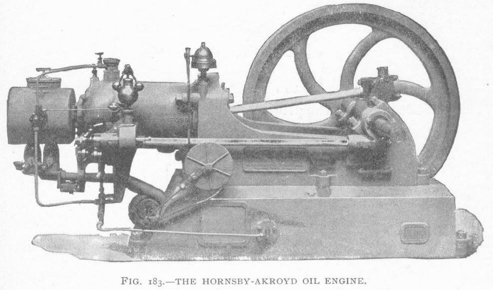
"The Hornsby-Akroyd Oil Engine"
"This engine is of English origin and now built by the sole licensees of the United States patents---the De La Vergne Refrigerating Machine Company---in all sizes from 4 to 55 H.P. They are of the four-cycle compression type, using any of the heavy mineral oils or kerosene as fuel.
This unique explosive engine seems to be a departure in design from all other forms of explosive engines, in the manner of producing vaporization of the heavy oils used for its fuel and the mannor of ignition.
An extension of a chamber from the cylinder head, somewhat resembling a bottle with its neck next to the cylinder head, performs the function of both evaporator and exploder. Otherwise these engines are built much on the lines of design as gas and gasoline engines, having a screw reducing gear and secondary shaft that drives the governor by bevel gear, the automatic cylinder lubricator by belt, and cams for operating the exhaust valve and oil pump.
The bottle-shaped extension is covered in by a hood to facilitate its heating by a lamp or air-blowpipe, and so arranged as to be entirely closed after the engine is started, when the red heat of the bottle or retort is kept up by the heat of combustion within. The narrow neck between the bottle and cylinder, by its exact adjustments of size and length, perfectly controls the time of ignition, so that of many indicator-cards inspected by the writer there is no perceptible variation in the time of ignition, giving as they do a sharp corner at the compression terminal, a quick and nearly vertical line of combustion, and an expansion curve above the adiabatic, equivalent to an extra high mean engine pressure for explosive engines.
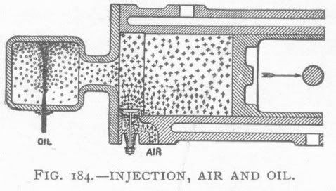
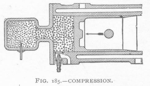
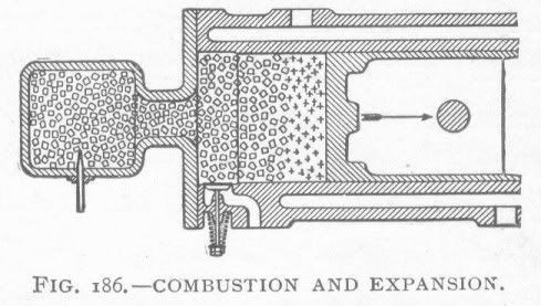
The oil is injected into the retort in liquid form by the action of the pump at the proper time to meet the impulse stroke, and in quantity regulated by the governor. Durring the outer stroke of the piston air is drawn into the cylinder and oil is vaporized in the hot retort. At the end of the charging stroke there is oil vapor in the retort and pure air in the cylinder, but non-explosive. On the compression stroke of the piston the air is forced from the cylinder through the communicating neck into the retort, giving the conditions represented in Fig, 184 and Fig. 185, in which the small stars denote fresh air entering, and the small circles the vaporized oil. In Fig. 185 mixture commences, and in Fig. 186 combustion has taken place, and during expansion the supposed condition is represented by the small squares. At the return stroke the whole volume of the cylinder is swept out at the exhaust, and the pressure in the retort neutralized and ready for another charge.
It is noticed by this operation that the ignition takes place within the retort, the piston being protected by pure air.
It is not claimed that these diagrams are exact representations of what takes place within the cylinder; never the less, their substantial correctness seams to be indicated by the fact that the piston rings do not become clogged with a tarry substance, as might be expected.
This has been accounted for by an analysis of the products of combustion, which shows an excess of oxygen as unburnt air; which indicates that the oil vapor is completely burned in the cylinder, with excess oxygen."

Fig1841897478x272.jpg


Fig1851897490x281.jpg


Fig1861897489x277.jpg


Dan
 
Chuck, can you make an adjustable cam for your trials? Until you find out the position the cam
is supposed to operate the injector, I mean. Possibly a lobe made by itself, with a couple of set
screws on a turned collar that will allow you to change the position of the lobe on a shaft that
drives the cam lobe. Then, when you find out where you want it, make a solid cam shaft.

Or, since you are driving the cam via gears, make one gear easy to rotate on its shaft, for
timing purposes.

This engine will run on a vaporous fuel, like gasoline or naphtha, right? It may not take a lot of
compression to ignite the fuel that's been super vaporized in something like a hot bulb. Seems
like it would just be begging to go off in an environment like that.
Then again, maybe I don't understand this at all!

Dean

 
Chuck,
It is obvious Find's engine design is nothing like the early 2 stroke oil engines like Mietz & Weiss engines. The latter used very low compression amounting to about 60-65 psi. Injection was directly into the cylinder mixing with the air and ignited upon contact with the hot bulb. Ignition timing was highly dependent on hot bulb temperature which was controlled with the introduction of water vapor into the combustion air. Water consumption increased with load. While quite effective, the addition of water to the combustion air greatly added to cylinder wear. The 4 stroke design appears quite different. Find has moved the injector to the cylinder just like the 2 stroke M&W design, as he says, to keep the injector and fuel cool. However, it appears his added vaporizer tube catches the fuel stream and directs the fuel into the hot bulb where it vaporizes. The vaporized fuel and combustion air remain separated during the intake stroke. As the piston compresses the air into the hot bulb, the bulb temperature ignites the fuel, and combustion progresses. As the Hornsby-Akroyd article suggests, the size of the of the hot bulb orfice is varied to get the required combustion timing. I think this area of the hot bulb is where much of the trial and error will begin since Find's vaporizer tube passes through this orfice also.

I own a Mietz and Weiss engine and I know the hot bulb must be almost a dull red heat before the engine will start easily on kerosene. Looking at the rather low intensity flame on Find's little preheat lamps, I don't see where he is putting that kind of heat into his hot bulb. That interests me greatly.
Jeff

 
Shred, I have agreed more or less with your theory, that the mixture ignites once it gets lean enough.

Dan, the pictures you posted confirms what I had thought I understood about the full size hot bulb engines.

Dean, yes, I can make an adjustable cam lobe. I don't think, however, the fuel injection timing is as critical to ignition as other factors such as those that control the timing of the air reaching the vaporized fuel.

Jeff, I've studied Find's pictures ad nauseum, but it hadn't occurred to me that the vapor tube was set up to "catch and redirect" the fuel into the hot bulb. Very perceptive on your part, the design makes a lot more sense to me now.

As complicated as this all seems, I'm not sure why I continue to pursue this. Must be a glutton for punishment!

Chuck
 
Chuck, I have been following this with great interest even though I can't add to the discussion. If it can be scaled down it will make a fantastic and unique model, and with your perseverance I am sure that will happen.

Regards,
Bill
 
I've decided to pattern my hot tube engine after my Henry Ford Plumbing parts engine. I scored a couple of 9" flywheels, so I'm scaling up the engine to a 1" bore x 1 3/4" stroke. This engine design is good for this type of project because everything is open and easily modified, added-to, etc., as required.

The cylinder will be made from the 1" plumbing tee in the picture. I've bored out the inside to to receive a cylinder liner that is 1 5/16" OD. I also counterbored the inside of the plumbing tee to form a water jacket around the cylinder.

The flywheel is now mostly machined. I still want to thin the spokes some since they look way too fat for my taste.

67beb8d2.jpg


Chuck
 
Still another turn. I'm now thinking I'll convert my existing plumbing parts engine to hot bulb operation. The construction is such that I shouldn't have too much extra work to do and the the changes needed for the hot bulb should be pretty easy.

Here's a photo and drawing of the hot tube I made. It's patterned very much after Find Hansen's hot tube although I had to guess at the dimensions. The material started out as 5/32" diameter drill rod 1 1/4" long. The hole through the center is a number 40 which is around .098" in diameter. The cross drilled holes are 5/64". The single cross drilled hole in the other end will be drilled after I make the hot bulb assembly and thread the hot tube into it, since the cross drilled hole has to be on top. Or I may just drill a through hole in the end of the hot bulb and use a nut on the outboard end so I can rotate the hot tube as needed.

842f183d.jpg


d7e01380.jpg


cc267c06.png


Chuck
 
Chuck,
I am glad that old text was useful. I think the key points made in it were the size and length of the hot bulb connection tube was the critical thing for ignition timing.

Find's models used a long connecting tube so the metal connection to the cylinder would not cool the hot bulb to much. Or at least that was my take on reading the pages.

It seams to me that if the connection tube was made from machinable ceramic the heat loss to the cylinder would be all but eliminated. The problem is all the machinable ceramic stock I have seen is a bit pricey.

The is a fantastic project and I will be watching your progress with interest.

Dan
 
Dan Rowe said:
Find's models used a long connecting tube so the metal connection to the cylinder would not cool the hot bulb to much. Or at least that was my take on reading the pages.
I was thinking that with a sufficient blowtorch on the outside of the hot bulb, faffing around with the remotely located vaporizer/injector could be done away with for a first engine ;) Good on ya for trying it Chuck.


The main reason, in my mind, for using the vaporizing tube is so the injector can be located away from the hot bulb and eliminate the need for water cooling the injector. If you place the injector on or near the hot bulb, you have to water cool it or the fuel in side will boil.

Chuck
 
Just a brief update to let people know I'm still working on the hot bulb engine. I've returned to the idea of building the engine from scratch instead of converting my plumbing parts engine. I've been wrestling with whether to make it a 1" bore or 1 1/4" bore. I've also been trying to come up with the best design for the cylinder / water jacket. I think I've got those questions settled as well. I've ordered the materials from Speedy Metals and should be getting that delivered early next week (tomorrow is probably too much to hope for!).

The engine frame will be made from 3/8" angle iron, 2" x 3". I've also settled on a 1" x 1 3/4" bore and stroke. I'm trying to keep the design as simple as possible and, at the same time, add enough bling to make it look nice.

The valve manifold will be on the side of the head and the single valve will act as both exhaust and inlet valve. It will be opened at the end of the firing stroke and held open through the exhaust stroke and the intake stroke, closing at the beginning of the compression stroke.

I was going to incorporate helical gears, but decided that simple spur gears along with other simplifying measures might inspire others to build it, assuming I can get it to run!

At the moment, I'm planning to use flanged ball bearings for the crankshaft, but that may change.

Here's a stylized drawing of what it will look like so far.

14e9233b.png


Chuck
 
Couldn't stand it any longer, I had to get out in the shop and do something. So I made the cylinder liner and the water jacket. The cylinder is turned from a 1 5/8" hunk of cast iron and the water jacket was turned from a 1 3/4" piece of steel tubing. Kept the outer diameter the same, but had to bore it out for an interference fit over the cylinder linder. Not sure why the texture on the outside of the tube is rough, but I kind of like it... looks like cast iron.

After all the indecision about whether to make it a 1" bore or 1.25" bore, I settled on .875" instead. The stroke will be 1.5"

59e320fd.jpg


7505cd3c.jpg


Looks good Chuck

Just wondering about the interference fit since I need to do similar soon. How much interference did you make? Are you going to press it in cold or shrink fit it?

Cheers
Steve
 
swilliams said:
Looks good Chuck

Just wondering about the interference fit since I need to do similar soon. How much interference did you make? Are you going to press it in cold or shrink fit it?

Cheers
Steve

Thx, Steve. The ID of the water jacket is about .003" smaller than the OD of the cylinder liner. I will put the cylinder in the freezer and heat the water jacket as hot as I can get it with my mapp gas torch. Hopefully the cylinder liner will just drop right into the water jacket.

Chuck
 
This looks really interesting chuck,

i've just scanned over it up to now but will have a proper read later.

Thanks for sharing :bow:

Nick
 
Hi Chuck

I did a quick calculation based on thermal expansion coefficients which I found here,

http://www.engineeringtoolbox.com/linear-expansion-coefficients-d_95.html

If I have things correct then for steel of 1" diameter you need to heat it up by about 230 degs C to get it to grow by 3 thou.

I might try an experiment with shrink fitting a brass ring on a bit of steel rod before I move onto the real thing

Sorry for dragging you off topic

Cheers
Steve
 
Chuck,

Steve's on the right track here....I get 213 C , or about 415 F


Dave
 
Chuck,
It would be a pain to find a leak after heat shrinking it together. Heat shrinking is better than pressing them together cold(relative to leaking), but silver brazing is quick and easy, and you are visually pretty assured of a complete seal.

Jeff
 
Rustkolector said:
Chuck,
It would be a pain to find a leak after heat shrinking it together. Heat shrinking is better than pressing them together cold(relative to leaking), but silver brazing is quick and easy, and you are visually pretty assured of a complete seal.

Jeff

Thx for the tip, not sure how successful I would be silver soldering cast iron to steel...

Chuck
 

Latest posts

Back
Top