Horizontal IC Engine 5/8" Bore

Home Model Engine Machinist Forum

Help Support Home Model Engine Machinist Forum:

This site may earn a commission from merchant affiliate links, including eBay, Amazon, and others.
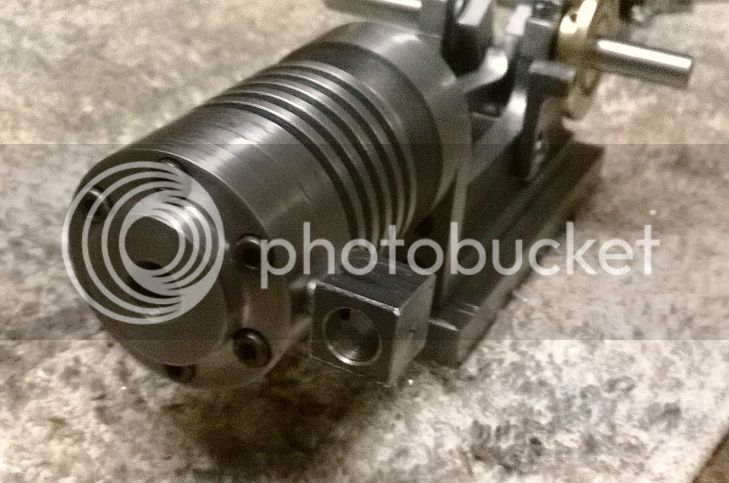
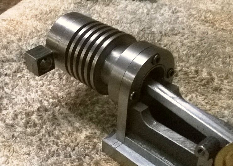
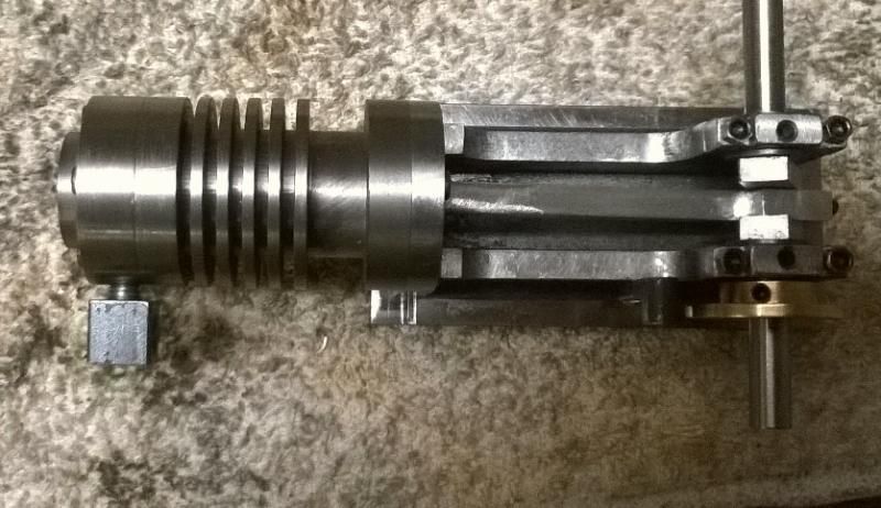
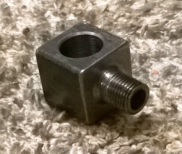
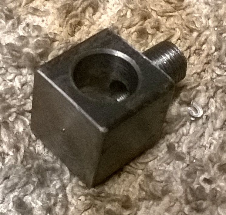
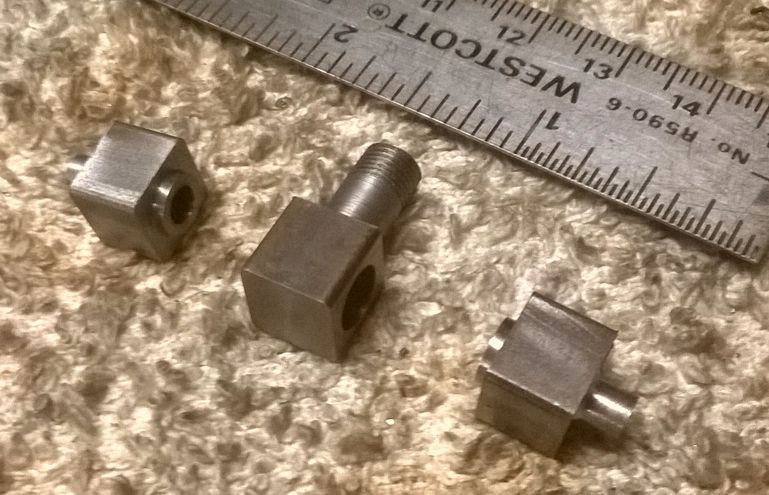
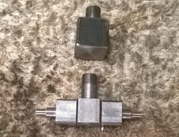
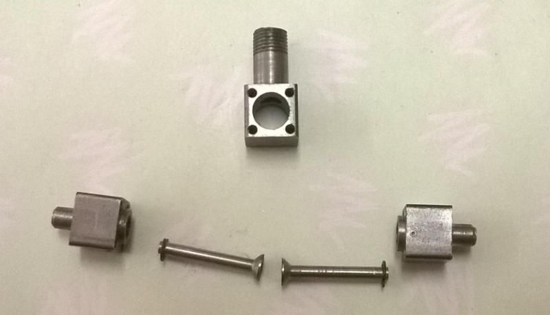
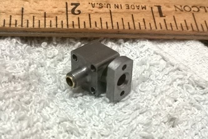
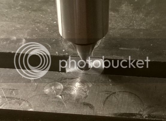
I settled on a design for the push rod carrier. Started with a piece of 1/4" thick steel, 3/8" wide and a little over 1" long. Mostly used the milling machine to shape it...

WP_20141025_002_zps17668ac9.jpg


WP_20141025_003_zps2c6e38fa.jpg


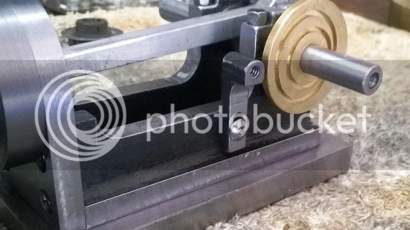
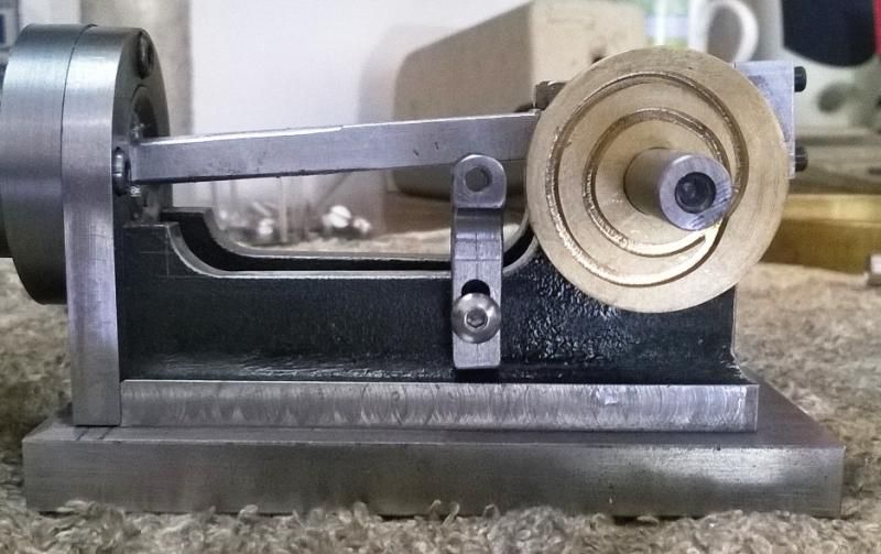
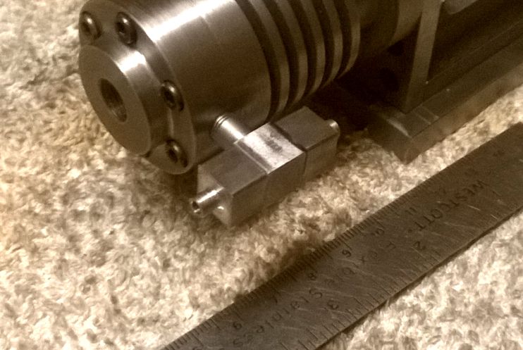
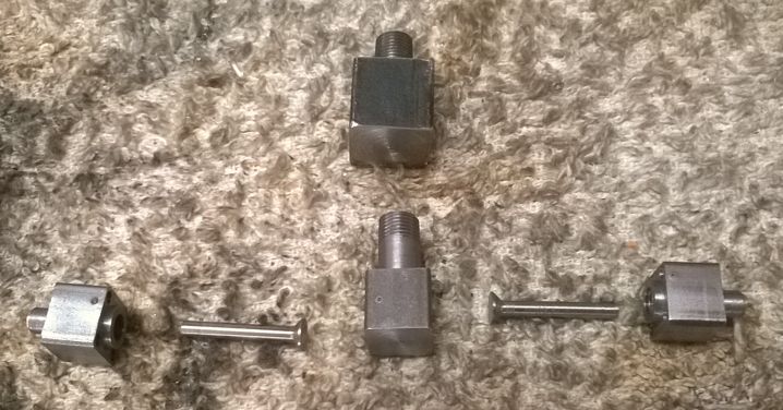
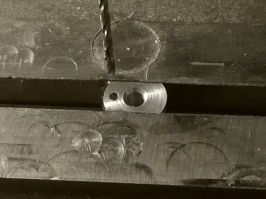
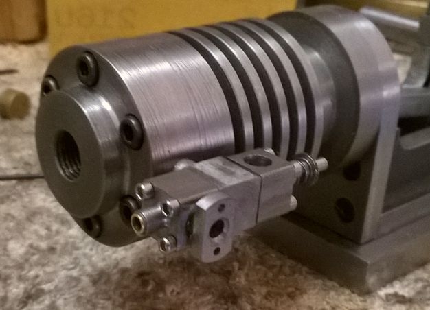
A single screw will go through a horizontal slot in the push rod and attach to the threaded hole at the top of the mount.

Chuck
 
Started work on the intake/exhaust assembly this evening. Guess you could call this part the manifold. The intake valve cage attaches to the front and the exhaust cage to the back.

WP_20141025_004_zps3eee3c61.jpg


WP_20141025_005_zps605c91fd.jpg


WP_20141025_006_zpsec8ddd16.jpg


I started with a 1/2" x 1/2" piece of square hot roll. The large hole is 5/16" diameter and will receive the intake valve cage on one side and the exhaust on the other. The spigot that screws into the head is 1/4" diameter and is threaded 1/4-40 model pipe taper.

WP_20141025_007_zpsd6e1e50f.jpg


WP_20141025_008_zpsd783fb1f.jpg


Next I'll start on the valve cages.

Chuck
 
That's coming along nicely Chuck,

Jim

Thanks, Jim.

I decided the manifold made from 1/2" square bar was a bit too bulky looking so I remade it from 3/8" square bar. And, I got a decent start on the valve cages.

WP_20141026_001_zpse264abac.jpg


WP_20141026_002_zpsdec99c89.jpg


Still have to drill and tap the mounting holes. I'll use 1-72 SHCS's to mount the cages to the manifold. This is a new level of smallness for me so it will be interesting. The valves will be made from 3/16" drill rod. Tomorrow I'll see if my local fastener supply store has 1-72 screws. I'm not hopeful, but they've surprised me before.

Chuck
 
  • Like
Reactions: gus
Today I made the valves from 3/16" drill Rod (aren't they cute?). I've included a picture of the first manifold I made from 1/2" bar stock for comparison to the new one made from 3/8" square bar.

WP_20141027_001_zps9d1c836a.jpg


And here's how it all fits together...

WP_20141027_002_zpsf1454795.jpg


In this picture, I've cut the grooves and installed the E-Clips which will hold the valves in place. I've also drilled and tapped the 1-72 mounting holes for the valve cages to the manifold.

WP_20141027_003_zps9d8ea2cb.jpg


Couldn't find any 1/2" long, 1-72 socket head cap screws locally so had to order some from Ebay. Probably won't get them until Friday, so I guess I'll move on to the push rod assembly next.

Chuck
 
I revisited the Cam Disk on Wayne Grenning's model of the 1883 Daimler engine and realized my design was all wrong. So I redrew it and milled a new one. This one, engraved on a 1" disk is smaller than the first which was 1.25". Here's a video of the CNC mill doing it's thing...

[ame]https://www.youtube.com/watch?v=1sXzMdXvEuY&list=UUZB8pRNp9Plbd0-T9RmyR9g[/ame]

And here's a picture of the finished cam...

WP_20141028_001_zps8ff25c1f.jpg


I'm anticipating this thing will probably not work right out of the chute and will require some tweeking, perhaps remaking, etc.

Chuck
 
I have also been thinking about the previous cam profile which appeared to be basically two circles. Not quite what is needed (but would probably work on this model).

I think we really need a normal cam profile on one revolution and a base circle on the next but I am not sure how to achieve this (or what the slider would look like). Lying in bed trying to visualise it didn't work so now I need to draw it and play. It is an interesting problem that someone who knows about railway points would probably solve immediately.

Jim
 
It is an interesting problem, Jim. One thing that complicates the issue is that the grooves have to be at a pretty good angle to each other where they intersect so the shuttle won't get "confused" as to which path to take.
 
  • Like
Reactions: gus
I'm not sure a normal cam profile on one revolution would be ideal. Remember this disc will spin at twice the RPM of a normal cam so the profile has to be stretched out.

It's a very intriguing design, I just wish I had CNC so I could have a go at it too.
 
  • Like
Reactions: gus
I keep playing with cam design (when I should be doing other things). I have tried constant velocity and constant acceleration for the lifting part but I can't find a really classy design for the rest of it.

It's an interesting exercise. But I will probably give up soon or be distracted by some other new thought.

Jim
 
Here is a video that will hopefully clear things up a bit.

[ame]https://www.youtube.com/watch?v=-g1FRLrs6Ls&feature=youtu.be[/ame]

Several times I almost decided to convert the engine over to a standard geared cam, but in the end I'm really glad I stuck it out. This thing seems to be working really well. The only concern I have at this point is how well it's going to wear. Hopefully, by keeping it clean and well lubricated, it'll stand the test of time.

Chuck
 
Chuck,

I'm glad you're sticking with this. It's a different design and really makes this project interesting. Hopefully, it will wear well in practice.

--ShopShoe
 
That's great Chuck, it works well and the valve stays open much longer than I thought it would.

And now I can stop playing with cam shapes and get on with some of the things I should have been doing.

Jim
 
I'm still trying to wrap my head around how it stays on the right track. Congratulations Chuck On making it work. I like it


Jeff
 
Gus,

I think you could do it. If your rotary table is on top of your X-Y table, you can reverse engineer it so that you would move X or Y the distance of cam actuation distance at a given part(s) of the 720 degrees of rotary table rotation.

Perhaps math wizards could provide a math function that would generate a table of values for mill table and rotary table movements to be followed.

As I seem to be attention-span-limited in my old age I would print the table and add a column to be checked as each step is completed.

Unfortunately, As much as I am intrigued by this type of cam I am not in a position to try it myself as I am not getting enough shop time because of home-improvement projects and several relatives that need help with daily life.

The whole concept is interesting and I think most of us are in this hobby (at least those who stay in the hobby) enjoy the challenges as much or more than the finished products we can put on display.

Good Luck,

--ShopShoe
 
Maybe this will help. Here is a picture showing the segments by quadrant of the cam disk.

DaimlerCamDisk_zpsed30cc43.jpg


The groove was cut with a 1/16" end mill and is 1/16" deep. The dimensions listed are to the center of the groove. The fixed radius arcs are easy enough to cut on a rotary table. The segments in the quadrants where the radius is steadily change would be a challenge.

This drawing is for a 1.25" diameter cam disk and I actually scaled my down to 1.125".

I'm happy to field any questions although I may not know the answer. :-[

Chuck
 
Now there's a challenge, it could be done with a rotary table mounted on a mill with digital readout. The main rads are no problem, when it comes to the transition between the inside and outside rads, a series of X Y coordinates worked out on CAD would allow you to slowly use the mill table to machine the rest. The more coordinates that you have the smoother the transition.

Paul.
 
  • Like
Reactions: gus
I'm doing fiddly-bit work now. Today I worked on the intake manifold. Here's a picture of the finished assembly. The intake manifold part is loctited into the valve cage...

WP_20141108_003_zps0d51429e.jpg


I started with a piece of 1/4" x 1/2" cold rolled steel. Chucked it in the lathe and cut a 3/16" spigot on the end. I also turned down the rectangular part to 7/16" diameter, also radiused to 7/16". After cutting it free, I chucked the spigot into my mini lathe and faced off the outer end that the carburetor will attach to. Then I mounted it in my milling vice. In the following picture, I'm centering the hole under the milling spindle...

WP_20141108_001_zps48aff3f8.jpg


Then I used the DRO to locate and drill the 1-72 screw holes.

WP_20141108_002_zpsb233f5d8.jpg


And, here's what it looks like on the engine.

WP_20141108_004_zps45e9d02e.jpg


WP_20141108_005_zpsf0db22e5.jpg


Next I need to wind a spring for the intake valve.

Chuck
 
Chuck--I just checked in my machinists handbook, and the maximum o.d. of a #1-72 fastener is .073". that is REALLY small. Hard for me to imagine putting a thread that small in to mild steel. Amazing work!!---Brian
 

Latest posts

Back
Top