Horizontal IC Engine 5/8" Bore

Home Model Engine Machinist Forum

Help Support Home Model Engine Machinist Forum:

This site may earn a commission from merchant affiliate links, including eBay, Amazon, and others.

cfellows

Well-Known Member
Project of the Month Winner
Joined
Aug 25, 2007
Messages
3,890
Reaction score
715
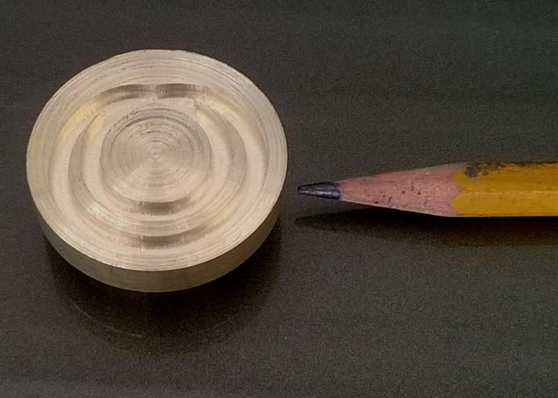
About time to get started on another engine. This will the smallest IC engine I've attempted with a 5/8" bore and 1.25" stroke. I want this to be another slow running engine and I think this is about as small as I can go without it sounding like a weed whacker.

HotBulb-5-8inchbore_zps790bc1dc.jpg


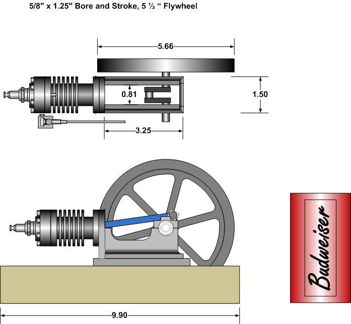
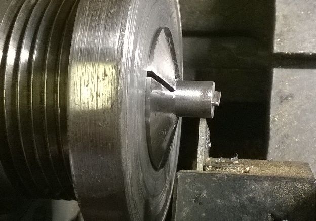
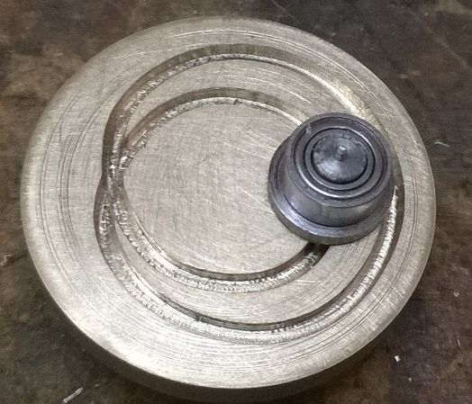
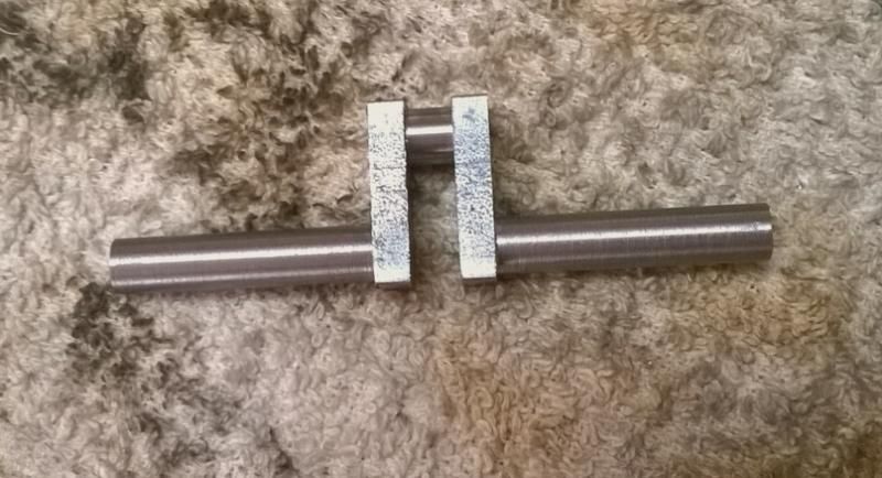
Didn't have a beer can for scale, so I had to fabricate one, 12oz by the way. The cylinder will be made from cast iron. I decided to go with air cooling because it's so much simpler than water cooling. The flywheel is 5.5", which is quite large for this size engine, more like some of the really early Crosley and Daimler engines. Hopefully this will let me attain the slower idle speeds I'm looking for. The engine will be throttled using the simple carburetor I designed. I'm going to try really hard to provide the drawings for parts as I go along.

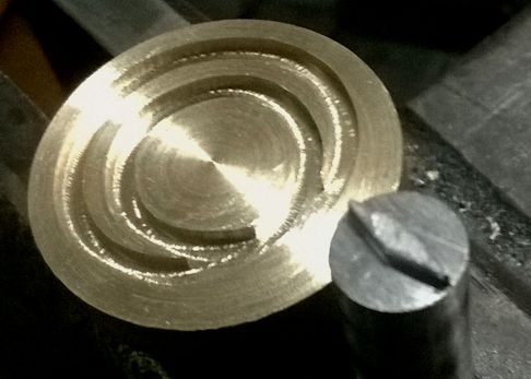
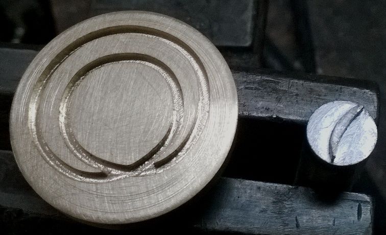
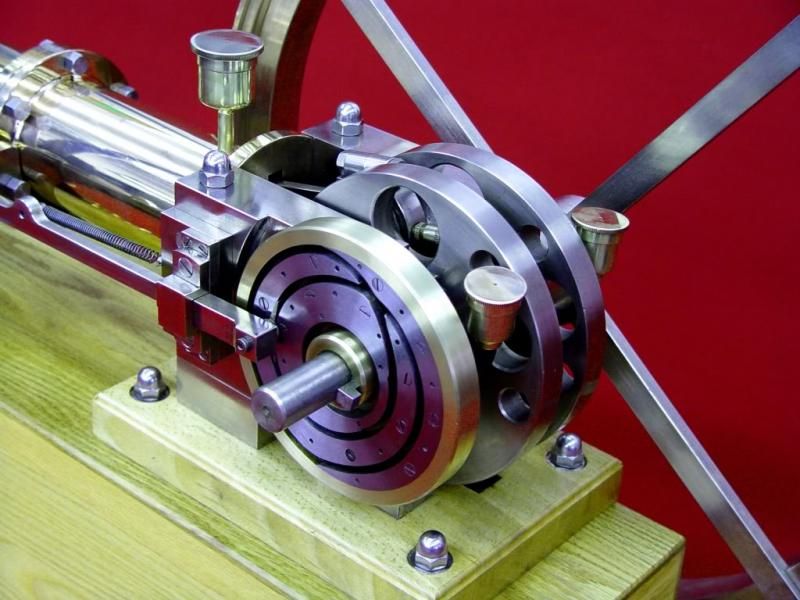
I'm toying with the idea of trying this CAM setup instead of the traditional geared cam...

DSC07862b_zps2c55225a.jpg


Chuck
 
Well of course you would try a different cam.

This looks like another project that I will be watching with interest.

Jim
 
Settling in for another great post :cool:
 
Hi brian,when i finish the beam engine i would like to make an ic engine
Dont know anything about them perhaps you can suggest/advise me
Simple as possible,interesting/slow movement and simple plans at a decent scale
for a free download.General questions.what fuel,ignition spark plug ad infinitum
Best regards barry
 
Here's my first go at making a cam disk. It's made of brass and the groove was cut with a 3/32" end mill. I may have to go with a smaller groove, maybe 1/16", although even 3/32" is going to be tough to make a shuttle for. I'm going to try to get the 3/32" to work.

WP_20141010_003_zpsf890261a.jpg


WP_20141010_002_zps3a0a9fc8.jpg


Chuck
 
Thanks, Brian. Did with CNC.

Here is a photo of my second attempt at a shuttle, machined using CNC on the end of a 3/8" steel rod. I had to file it down some to get it to ride the groove all the way round.

WP_20141010_004_zps323c2a17.jpg


Preliminary results are promising although I'll need to lash it up in a functional assembly to see if it's going to work. I think a thinner shuttle running in a thinner groove would follow better and I may have to resort to that but I'll try to get this one working first.

Chuck
 
Last night I was trying to fit a bearing to the cam follower when it popped out of my vise and disappeared into nether regions of my shop. So, I stopped for the night and today a made a new one.

Since I had to make a new cam follower I decided to modify the cam disk with a 1/16" groove instead of 3/32". Since I had plenty of meat on it, I mounted the cam in my lathe and faced off the 3/32" groove. Then, using a 1/16" end mill, I milled a new groove along the same profile.

WP_20141011_001_zpsdbc47400.jpg


I did a bit more research on this cam style and discovered that I had the profile wrong on the follower I had made. So, the new cam follower has a crescent shape rather than the eye shape. I chucked the 3/8" rod with the cam follower shape on the end and prepared to neck down the back of it for a ball bearing race.

WP_20141011_004_zps54712a0f.jpg


Then I parted it off and fitted the 5/32" ID ball bearing to the back of the cam follower. Here is the follower with the bearing sitting in the groove on the cam disk.

WP_20141011_005_zpse4260edd.jpg


I did a preliminary test by mounting the cam disk in my mini lathe and held the cam follower in my fingers as I spun the lathe over slowly. It seems to track exactly as it's supposed to, so I'm pumped. So, now I'll design he carrier for the cam follower and we'll see where that leads me.
 
I feel confident enough about the gearless cam arrangement so I'm back to working on the engine design and drawings.

I've attached the drawing of the engine frame. It may go through some changes so I'll try to give a heads up if that happens.

Chuck

HotBulb-5-8 inch bore.jpg
 
Glad I am not the only one to have little parts pop out of the vise and 'hide' themselves somewhere....

Very interesting start - going to be following along! ... where IS that popcorn?...
 
Glad I am not the only one to have little parts pop out of the vise and 'hide' themselves somewhere....

Very interesting start - going to be following along! ... where IS that popcorn?...

Thanks, the lost part reappeared today. I decided to give the shop a thorough cleaning before I start making chips and I found the part laying on the floor. Strange I couldn't find it the other night.

I've attached the preliminary drawings for the Cylinder and the Head. Again, these might change.

I'm doing the drawings in Visio and when everything is done, I'll use Visio to publish the entire set of drawings into a single PDF file. These preliminary drawings are more to give folks an idea of how this will go together. Hopefully I'll get some feedback if anyone notices any glaring errors or omissions!

Chuck

Cylinder&Head.jpg
 
Me think the shuttle should look like a "moon sliver" two arcs intersecting to pilot itself in the right loop. A lozenge shaped shuttle can go either way.

Is the assemble engine a rendition? Great 3D drawing .

I did not see the new follower when I wrote this. Sorry.
 
Last edited:
Me think the shuttle should look like a "moon sliver" two arcs intersecting to pilot itself in the right loop. A lozenge shaped shuttle can go either way.

Is the assemble engine a rendition? Great 3D drawing .

I did not see the new follower when I wrote this. Sorry.

Hey, Mauro, thanks for dropping in. The drawing was all done in Microsoft Visio. It has gadient shading capability which gives the illusion of 3D. Very helpful in visualizing things while still basically in 2D.
 
Meager beginnings. I spent most of the day doing a deep cleaning of my shop. Cleared off and vacuumed all the work surfaces, lathe and mill. Did a bit of reorganizing vacuumed the entire floor, even under things as far as I could reach. It's amazing how much a clean shop motivates a person to do something creative, kind of like blank canvas I suppose.

So, I started on the frame. I cut a couple of 3.3" lengths from a 1.5 x 1.5 x .25 piece of angle iron.

WP_20141012_006_zps260b59ff.jpg


I cut one leg of each piece with my bandsaw, then used an end mill to finish off the outer edge.

WP_20141012_007_zpsb1434913.jpg


Finally, I milled them down to 3.25" long, squaring up the cylinder end in the process. Next I'll cut and mill the height down to 1.25" and mill the curved section in the side.

Chuck
 
I spent about 4 hours in the shop today getting the engine frame pretty well together. After markup, I started with some band saw work...

WP_20141013_001_zps57520ce8.jpg


Then it was on to the mill...

WP_20141013_002_zps2c7359df.jpg


I cut the arcs by plunge milling with a half inch end mill, starting at the outer edge and moving in about .030" for each plunge until I reached the bottom of the area to be shaped. I then used the band saw to cut out the waste and finished with an end mill.

WP_20141013_003_zpse4a7cc30.jpg


Then I shaped the curve on the back of the frame, this time using a 5/16" end mill.

WP_20141013_004_zps30262e96.jpg


Here, I've got everything super-glued together. The 3/4" bar in the middle is a spacer to hold the two outside frame members parallel and property spaced. I had already drilled the holes in the bottom plate. I inverted this assembly and used those holes to mark and partially drill the holes in the frame sides. Super glue works pretty well, but only for making a small start with the drill bit. Invariably the glue lets go if there is too much heat or vibration.

WP_20141013_005_zps589d8ed5.jpg


After drilling and tapping the holes in the frame sides, I enlarged and counter bored the holes in the base plate. The following pictures show the assembly bolted together.

WP_20141013_007_zps8ad9fe08.jpg


WP_20141013_008_zpsc31425e7.jpg


WP_20141013_009_zpsaeaf7197.jpg


Next it's on to the front frame member that will hold the cylinder.
Chuck
 
Today I worked on the Crankshaft. I started with a piece of 1" x .375" cold rolled steel 3.5" long. Here I've made cuts to relieve all the stresses and laid out the rough lines. These lines are just for reference.

WP_20141016_001_zps6d9992b3.jpg


After I had made the cuts, I measured and drilled 2 center holes on each end, one for the main journal and one for the connecting rod journal. These were done in the milling machine vise, using the DRO to make the measurements. Here I've got the blank mounted between centers in the lathe, ready to cut the connecting rod journal.

WP_20141016_003_zps13dc2bc6.jpg


In this next picture, I've finished cutting the connecting rod journal

WP_20141016_004_zpsd94e261e.jpg


And here I've cut away the waste

WP_20141016_005_zpsebe9f370.jpg


And this final picture shows the finished crankshaft. The journals are all 5/16".

WP_20141016_006_zps1a1e626f.jpg


Chuck
 

Latest posts

Back
Top