Flame Eater begins...

Home Model Engine Machinist Forum

Help Support Home Model Engine Machinist Forum:

This site may earn a commission from merchant affiliate links, including eBay, Amazon, and others.

winklmj

Well-Known Member
Joined
Nov 23, 2009
Messages
171
Reaction score
2
Time to start on the Jan Ridder's Flame Eater. This will be a slow build for me as I only get a few hours to work now and then. 2nd engine, first time working with cast iron and doing any deep boring, etc... Should be a fun learning experience. My machines are in "inches" so I'm converting from metric and fudging the numbers when I can.

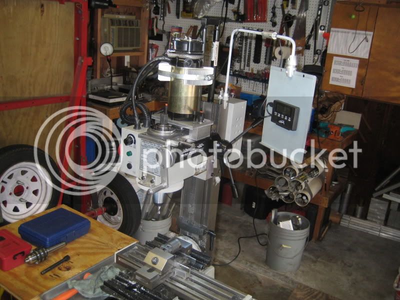
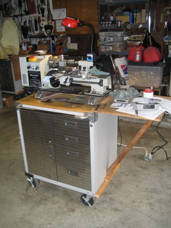
The "shop". Has to be cleaned up and rolled away every nite so the cars can go back inside (major PITA):
IMG_2391.jpg


I turned the cylinder OD yesterday. Sorry--no pics. Got to use my 1-2" mic for the 1st time.

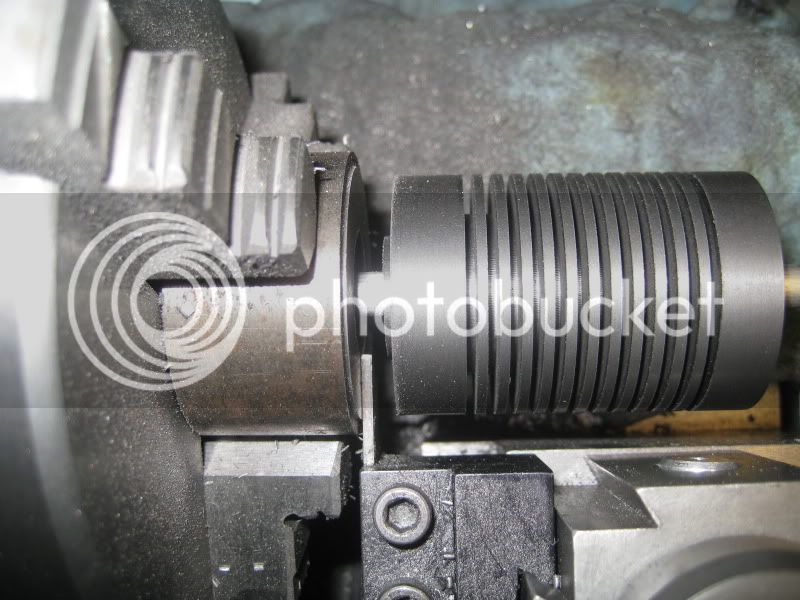
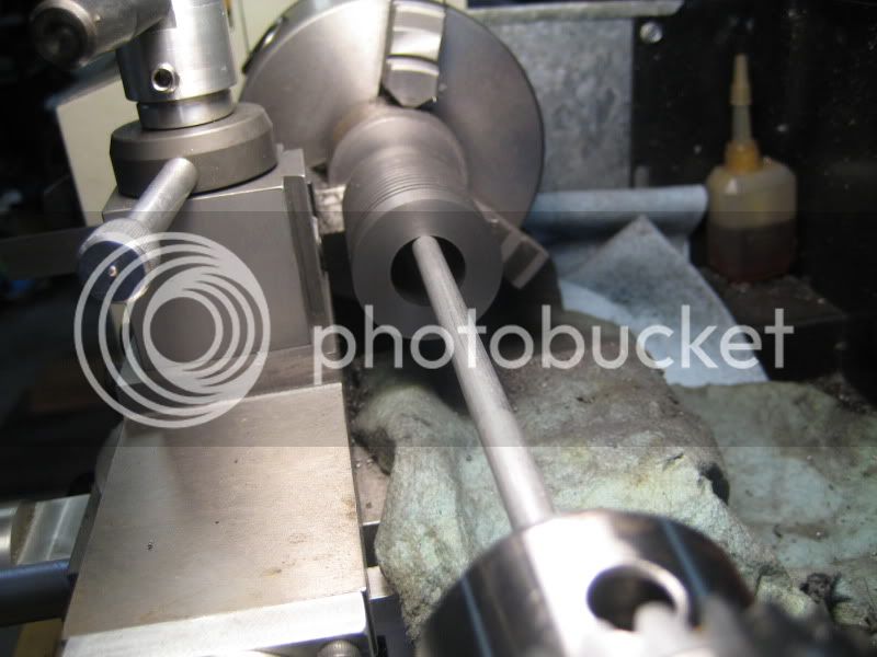
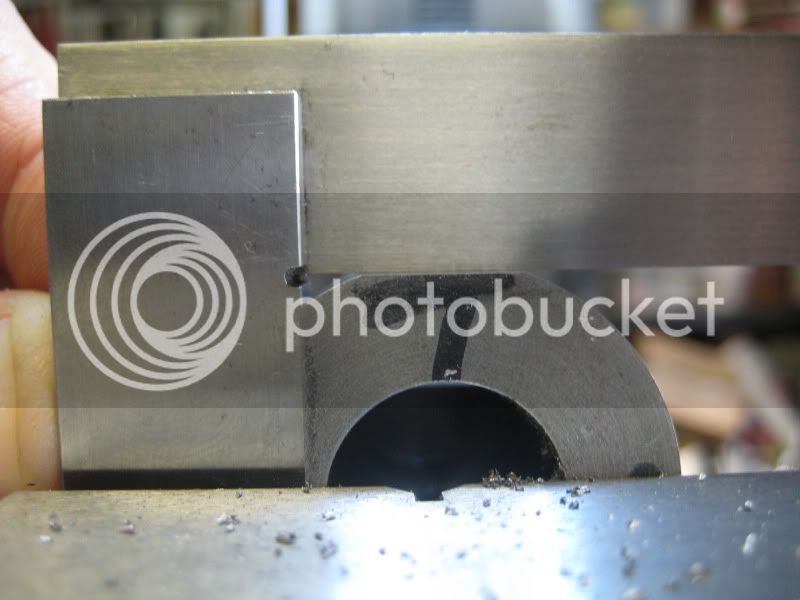
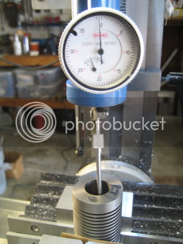
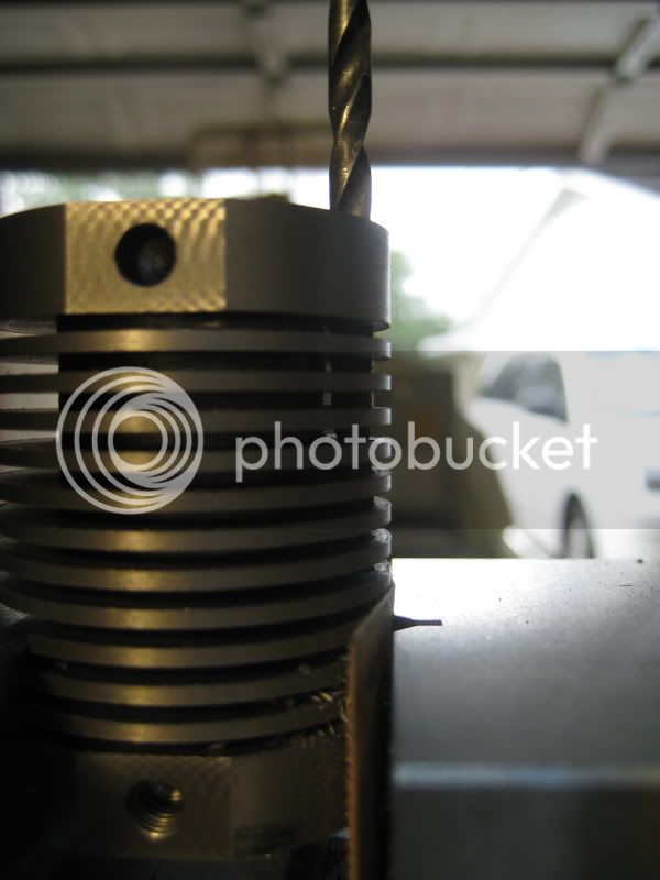
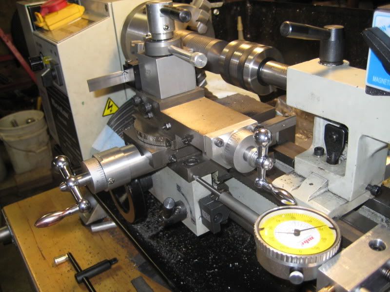
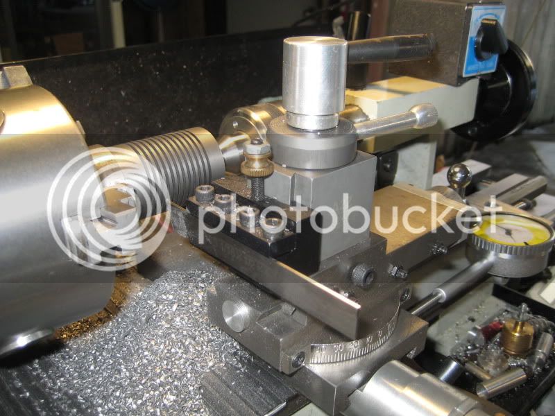
The fins setup. Got to use my home-made carriage-stop/DI-holder and 2" DI:
IMG_2386.jpg


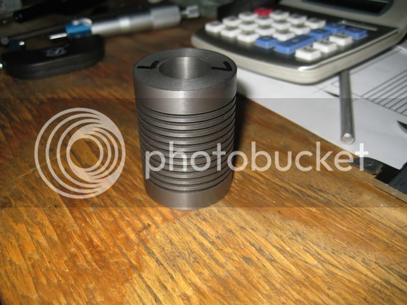
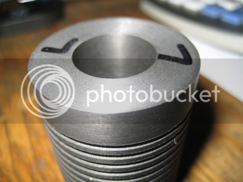
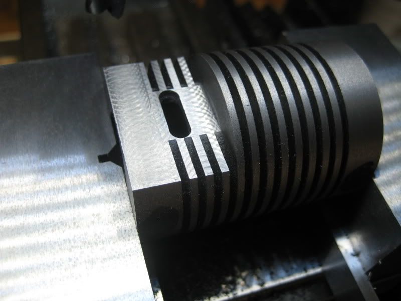
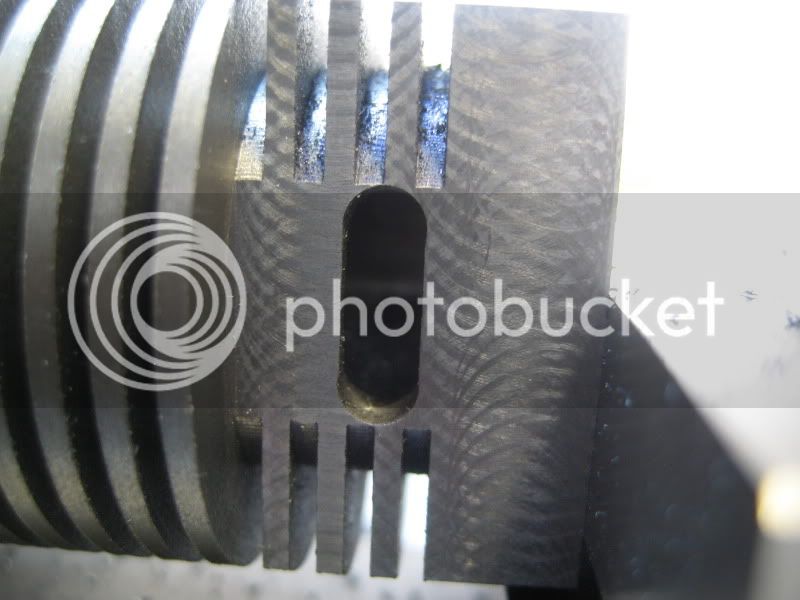
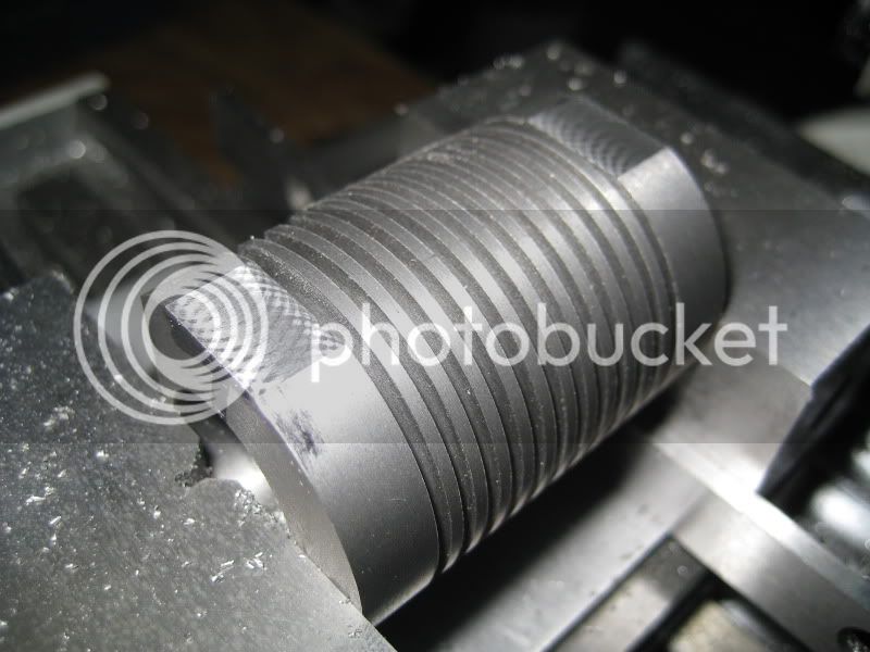
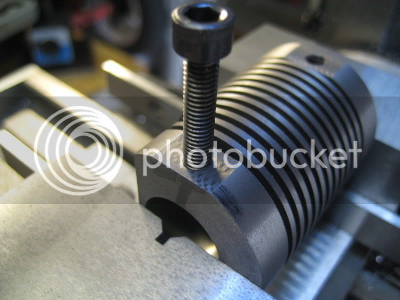
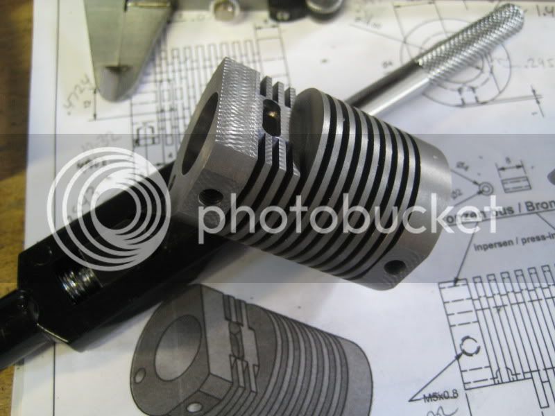
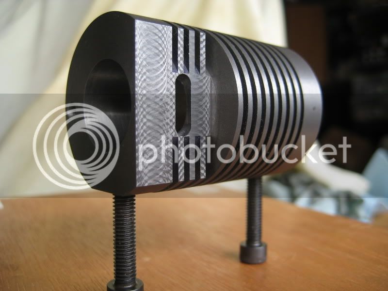
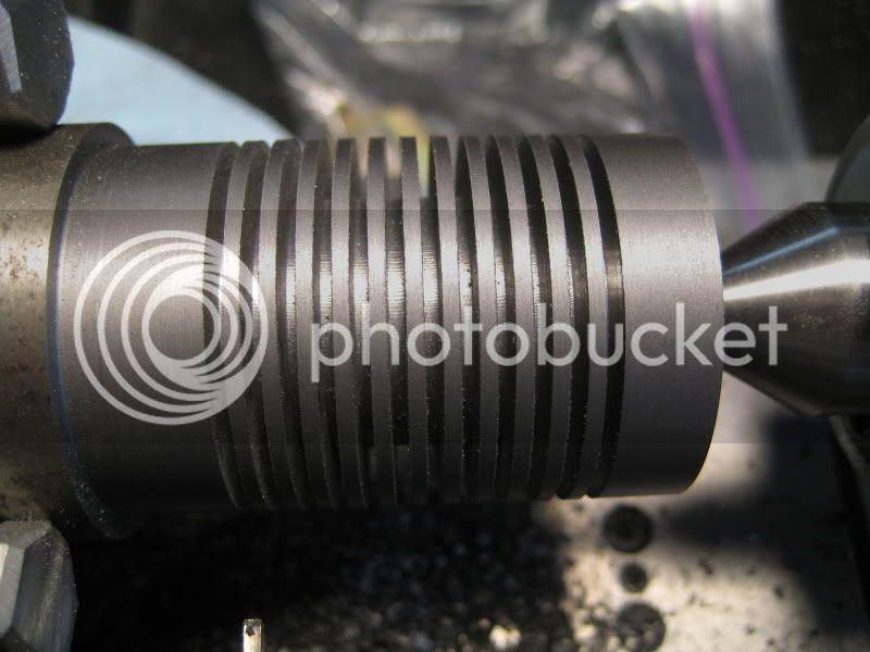
Just finished up the cylinder fins.
IMG_2387.jpg


Turned out OK I think. I don't have a 2mm tool and didn't want to grind one--so 1/16" is close enough and I recalculated the dimensions ending up with a few more "thinner" fins than on the plans. I don't think it will matter but if it does I've shot myself in the foot from the very beginning:
IMG_2388.jpg


More as it happens.
 
That's a nice start! Making fins right off the bat makes for a nice show.
I think you're right, the fin width shouldn't matter for this piece.

Thanks for the new thread!

Dean
 
How do you like the microlux lathe? I am debating on getting a 7x16 microlux. How is the quality? I like the fins btw keep up the good work Thm:
 
The Microlux lathe is OK--typical of all the other SIEG 7x machines. I got it because of the extra-length, cam-lock tailstock, and the tru-inch dials. Not having to clean all the goop off was a bonus. It still needs tweaking just like the other 7x machines. I have the Microlux mill to go along with it. If I had more room or a dedicated shop I'd want bigger machines.


Jan calls it the "Flame-eater with internal valve".
 
Nice start, I'm sure the fins will be absolutely fine! Watch out when it comes to drilling the long hole for the valve rod, this is where mine almost got ruined.

Vic.
 
Omnimill said:
Watch out when it comes to drilling the long hole for the valve rod, this is where mine almost got ruined.

Mind sharing how so? Binding as it breaks through each fin and wants to wobble off center a bit maybe? I'll use a freshly sharpened bit.
 
winklmj said:
Mind sharing how so? Binding as it breaks through each fin and wants to wobble off center a bit maybe? I'll use a freshly sharpened bit.

I very carefully set the cylinder up in the vice on my mill but the drill still wandered. If I was doing it again I would mark and drill from both ends - unless anyone else has some good ideas? :-\

Vic.
 
Started with the part that is the most fun to make, huh? I don't blame ya. Nice job, the pics are good too. I'm getting ready to spin the fins on my Hit 'N Miss.

-Trout
 
Bored the cylinder this evening. No boring boring pics :)

Parted off:
IMG_2395.jpg


Something to catch it when it's cut loose:
IMG_2394.jpg


Flipped and faced off to final length.
IMG_2407.jpg


I must've made 10 spring passes when boring it out. Ended up about 2-thou oversize--no biggie but I was trying to hit it dead-on. My hole gauges say it's pretty darn close all the way through--at lease as best I can measure with them--certainly within the 3-thou Jan recommends.
IMG_2408.jpg


Must lap it still--dowel and some valve grinding compound maybe?

Onto the mill next.
 
Wink,

I made two cylinders when I made mine, and by using the bore test bar as the final lap, both ended up perfectly parallel and the same size. Then it was just a matter of turning the pistons to fit and very gently lapping them to the bores. The better you can get them at this stage, the better it will run.

The same goes for the sliding valve, it should be 'silky' smooth in the bore without any lubricant.

If you are using the later plans, with the bearings at either end of the operating rod hole, you shouldn't have any difficulty. I would check on which version you have, as the ones with the bearings in either end makes drilling the hole a piece of cake. The earlier version required a long series drill to reach thru the length of the cylinder (I used the old version and it was a pain making up the longer drill).

http://www.homemodelenginemachinist.com/index.php?topic=2084.0

There have been a few builds on here of that engine, so I would suggest you root them out and have a read (or get the lads to give you the links to their posts), then any problems you are liable to encounter have already been pointed out, and you won't make the same mistakes.

BTW, by the time you get it running, you will realise just how fickle they are to setting up. But don't give up, because they are a fascinating engine to run.

I can't seem to be able to find my original build, maybe it was one of the ones lost when we moved to a private host, but here is a follow up, and does contain some info on burner types and positioning.

http://www.homemodelenginemachinist.com/index.php?topic=212.0

http://www.homemodelenginemachinist.com/index.php?topic=350.0

Keep going, by the looks of what you have already done, you will have no trouble getting a good runner.


Bogs
 
Bogstandard said:
...by using the bore test bar as the final lap, both ended up perfectly parallel and the same size. Then it was just a matter of turning the pistons to fit and very gently lapping them to the bores.

Not sure what a bore test bar is. Did you have something previously turned the right diameter that you used? I was measuring with something like these:
200px-TelescopicGauges155-905.jpg


I had searched for lapping tips earlier and found the wood dowel and paste, flap disks, or brake-cylinder hones. I don't have an adjustable reamer so that's out. Should I even bother lapping at this point (and risk getting something out of round) or do it after turning the piston and valve and then just run them in with each other?

 
Wink,

If ever I am making a very critical bore, I always make up a test bar, one end exact size, and the other end 0.002" smaller. Both about 1/4" longer than the bore length.

Use the small end until it just slides in, then use the exact end for your very fine boring to size.

I use a brass test bar, then when it gets to exact size fit, I put a tiny bit of fine abrasive on the test bar and lap to final finish, feeding from both ends.

I find that this is the quickest and easiest method for me to get a perfect bore. Other people have their own methods.

Then make your piston to a tight sliding fit, then a very fine lap of piston to bore.

I would only use this very close fitting system on this type of engine, and where both piston and cylinder are of the same material. Other types normally require larger running clearances, especially if rings are being used. But I would still use the test bar for doing the bore.


Bogs
 
Bogstandard said:
If ever I am making a very critical bore...

Good tip. Thanks for that. I'll use it next time ;D For now I guess I'll turn up a lapping bar and go at it with some paste. And then lap a bit more with the piston and valve once they're made.
 
On to the Mill. My z-axis DRO sure comes in handy. (I have scales for the x and y too but have been too lazy to install them):
IMG_2419.jpg


Flame flat and port. The flat was easy (or so I thought) . I don't have any metric end mills. The smallest center-cutter I have is 3/16". So I drilled 3 4mm holes then ate away at the remainder with my the side of my 1/8" ball-end mill (the tinyist I have):

IMG_2414.jpg


Then looked at the plans and figured out I didn't make the flat long enough and had to mill away one more fin.

Port close up:
IMG_2434.jpg


Flats for the cylinder mounts were next:
IMG_2421.jpg


They came out pretty square:
IMG_2432.jpg


Center drill, drill, and tap 10-32 (converting to inches where I can):
IMG_2440.jpg


Struggled with how to setup for the push-rod hole. I knew the diameter but couldn't figure out how to accurately pick up the edge of the cylinder. Decided to use my co-ax indicator and find the center then offset from there:
IMG_2443.jpg


Drilling 4mm:
IMG_2450.jpg


I wandered off by about 5 thou (as best I can measure) at the opposite end. I don't think it'll be any trouble. I proably shoulda' done this in two steps maybe 2mm followed by a 4mm.

Done with the cyl for now:
IMG_2454.jpg

IMG_2461.jpg


A bit of a break then back at it this evening.


L8er,

Mike
 
Good work Mike,

I for the bore on mine I just reamed it with an adjustable reamer and the finish was good enough straight from my lathe on the piston.

The beauty of the cylinder is, not much of it is critical - only the size and position of the port, the squareness you mentioned and the position of the hole for push rod don't matter!

Nick
 
You made great progress, Mike. Thanks for all the great pics!

Dean
 

Latest posts

Back
Top