Fixing a Wonky crankshaft

Home Model Engine Machinist Forum

Help Support Home Model Engine Machinist Forum:

This site may earn a commission from merchant affiliate links, including eBay, Amazon, and others.

Brian Rupnow

Design Engineer
Project of the Month Winner
Joined
May 23, 2008
Messages
14,996
Reaction score
8,292
Location
Barrie, Ontario, Canada
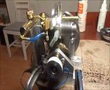
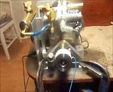
Enough time has gone by now, that I can start thinking about the wonky crankshaft on my opposed piston engine. Through trial and error I have weeded out the carburation issues, the flywheel issues, and now the only real issue remaining is the crankshaft. The engine runs great. The crankshaft seems to be good everywhere except for the portion that extends out past the front bearing. I built the crankshaft in pieces, and held the two ends in a jig for my final assembly, hoping that would yield a nice straight crank, but sadly that was not to be. There is considerable run-out as can be easily seen by looking at all the bobbing and weaving that aluminum hand-wheel on the front of the crankshaft is doing while the engine runs. It doesn't do that on the flywheel end---seems to run "true as a die" back there. I really don't want to build a new crankshaft. My plan is to remove the crankshaft from the engine, cut the front off the crankshaft right beside the "throw" nearest to the front bearing, hold the flywheel end in my 3 jaw chuck, and bore the "throw" 13/32", then make up a new end which is .375" diameter over its full length except for the bit that extends through the 1/4" crank throw, which will be 13/32" diameter. I now have a tailstock chuck for my lathe with a bearing on it so that it can rotate freely. I am considering holding the flywheel end in the main chuck, holding the new end in the tailstock chuck, and silver soldering the final joint while the part is held perfectly aligned in the two chucks. There won't be enough heat transfer to damage either chuck, and if it doesn't work, I can then build a whole new crankshaft.-Nothing ventured --Nothing gained!!! To see what I am describing as "Wonky" click on the video link and watch that front aluminum wheel.
 
Hi Brian
I can vouch for the two chuck method of keeping alignment, I have used it on many jobs even welding, Protection of the lathe bed and chucks is of course important as I am sure you realize I also only lock the tailstock with the smallest amount of pressure to allow it to move back if the component expands
The other Brian
 
Before I begin to tear everything apart, I decided it would probably be a good idea to measure just how much "Wonkiness" my crankshaft actually had. Measurements with my dial indicator show a total runout of 0.013" on the flywheel side, which means only 0.006" out of true center. This I can live with, because it really isn't all that noticeable---in fact I didn't see it at all with the engine running. However, on the front side of the engine where that knurled aluminum wheel is, there is a total runout of 0.038"--which is .019" out of true center---And that is very noticeable. I hope I will be able to repair the bad side of the crankshaft without introducing more "Wonk" to the good side.

 
As to using the lathe as a soldering jig, well, its your lathe. I just don't like the idea of expecting a silver-soldered crankshaft to run true without subsequent machining. I'll stick my neck out: you might be lucky, but it ain't engineering. Putting it baldly, if you want a proper job, do the job properly!
You did ask.
 
" hold the flywheel end in my 3 jaw chuck, and bore the "throw" 13/32"

You are already starting to introduce errors, with the best will in the world a 3-jaw will be a bit off, add to that a drill chuck at the other end and you are not starting off on the right footing.

I think I would hold it by the flywheel end in a collet or 4-jaw if you don't have true collets. With a packer between the webs drill a light centre hole in the other end. You can then skim the end down which will make it true to the other end. just make some sleeves for the parts that fit on the now smaller end.

J
 
My 3 Jaw is out .003". I can live with that. The crankshaft is out by too much at the wonky end to skim it down to any useable dimension.
 
Dang--What a miserable little piggy to get the crankshaft out of. No worse than any other engine I suppose, but an hours work to get everything apart. the right hand end of the crankshaft is the end I will be replacing.
 
I started the hole with a centering drill in the tailstock chuck, then drilled through with a 1/4" drill, then an 11/32" drill, then figured out that I don't have a boring tool small enough in diameter to fit into the hole for a final bore. I hunted around and found that I did however have a 13/32" reamer that was practically new, so I used it to finish the hole. It appeared to be running true with no discernible wobble, but I will throw my dial indicator up on the finished hole to check for any possible run-out. Assuming the reamed hole is concentric with the part held in the chuck, my next trick will be to machine a new 3/8" shaft with a 13/32" dia. end on it to silver solder into the newly reamed hole.
 
I wasn't real happy with the results from reaming the crankshaft. When I put the dial indicator on it, the hole was about .008" total runout. So--I ground the backside of one of my cheap and nasty carbide tipped boring bars so it would fit thru the hole and bored out another couple of thou. Now the runout on the hole measures at a total runout of 0.003" which is about as good as it gets with my 3 jaw chuck. I can live with that.
 
Brian,

A quick question. .003 sounds like a lot to me. Regardless of the chuck accuracy, shouldn't the bored hole run true within the tolerance of the spindle bearings? Or did you pull it to admire your handiwork and then rechuck it before measuring the runout?
 
Well, so far so good. One picture shows the new shaft in the chuck. Damned thing turned out a bit blurry, but I started with 1/2" cold rolled steel, turned the full length to 0.412 (which was .001 to .002smaller than the hole that was bored in the existing crankshaft---I want the silver solder to be able to run into the cavity and not all "freeze" on the surface). Then turned the remaining length to 0.375".
The next shot shows it set up in my lathe, ready to silver solder. The inside where the rod journal is, is coated with "Wite-Out" which does a good job of keeping the silver solder away from places you don't want it. The white stuff on the other side is flux. The last picture shows it with the silver soldering finished. It is setting in the chuck cooling off now while I post this.


Thayer--You are correct. It was probably the fault of my measuring set up that I seen .003" after boring. My dial indicator is good for measuring runout on the outside of diameters, but gets pretty questionable when trying to measure the runout on the inside of a bored hole.---Brian
 
I'm pleased!! when I released the tailstock chuck and slid it back out of the way, the very end of the new shaft had about .008 total runout as I revolved the lathe headstock chuck. I have noticed that this tailstock chuck with bearings has a bit of "sag" to it because it sticks out a long ways from the tailstock body. (Its a cheapy, what can I say?) I took my trusty dead blow hammer, and with a bit of judicious tapping was able to come up with basically zero runout at the tip of the new portion of crankshaft, and about .002 total runout right in next to the "throw" it is silver soldered to. These crankshafts for two cylinders are like a piece of spaghetti ---if I do this again I will use a 1/2" crankshaft, not 3/8". Now I have to put in the keyway. It only took an hour to tear this engine completely apart. Probably it will take at least half a day to reassemble the thing and reset the valve and ignition timing.
 
There has been a slight change in the game plan. I thought that while I have everything apart anyways, this would be a good time to put ball bearings into the opposed piston engine to support the crankshaft instead of the bushings it was originally equipped with. Two years ago I had built version #1 of my cone clutch, which didn't work out terribly well, and lead to the construction of clutch #2. ---Clutch #1 has been setting up on a shelf for two years, so today I opened the CAD file to see what bearings were in it. As it turns out, it had a 3/8" sealed ball bearing in one end (perfect) and a 12MM sealed bearing in the other end (Not quite so perfect but can be made to work.) So--The 3/8" bearing which measures 0.376" wide x 1.126" diameter will be sunk into a full depth counterbore in the 1/2" thick frontplate of the engine. The 12mm brg. will get a steel sleeve .375" i.d. x 12mm o.d. loctited to the inside of the bearing, and fit into a full depth counterbore in the 5/8" thick backplate. The 12mm brg. is 1.260" o.d. x 0.391" thick. I do this fairly often---Dismantle something that didn't work out just as I had planned and save any purchased components out of it to re-use somewhere else.
 
So--We now have ball bearings front and rear. When I bore these blind holes to support a bearing, I don't try for a press fit. Just a "good sliding fit". The reason is, that no matter how accurate the boring work is, something always drifts a few tenths, and when you reassemble everything and snug it down, you introduce some bind in the bearings. I coat the outer diameter of the bearings with 638 Loctite, put in a "dummy shaft" that I have checked for straightness, and then torque everything down tight.--remember--both the front and rear bearing support plates are dowelled to the baseplate, so the plates themselves can't move around at all. The bearings will move around a little bit in the bores while the Loctite is still liquid, and come to rest in the "least stressed" position. Then when the Loctite sets up, the bearings are held solidly in place, in a position that has the least amount of stress on them.

 
Here we are, back where we started. Measurements show that I still have .008" total runout on the flywheel, so nothing changed at that end. However The other end that was so bad now measures .002 to .003" total runout. I am one step away from calling this a successful mission. I still have to start and run the engine and take a short video, then we will put this thread to bed.

 
And here we have it. The perfect end to a story. The engine runs well, the crankshaft no longer wobbles. I can end this post on a positive note, and put the engine up on a shelf with its many brothers and sisters. Now, if ever I'm called on to demonstrate the engine to anyone, I don't have to explain to anyone "Why that aluminum part on the front there jumps around so much"!!!
 
Brian,

I followed this from the beginning. It's really running nicely now. Congratulations and thanks for sharing.

Have you tried it with one of the machines you have made to see how it runs under load?

Thanks again,

--ShopShoe
 

Latest posts

Back
Top