Edwards Radial 5 Build

Home Model Engine Machinist Forum

Help Support Home Model Engine Machinist Forum:

This site may earn a commission from merchant affiliate links, including eBay, Amazon, and others.
My first experience with a radial engine was at McCord AFB Tacoma, Washington around 1960...
My Father was in the USAF and he used to take me out to the flight line to see the C-124's that he worked on...
He was a Recip mechanic...A&P
I can still hear it today and will always be with me...
There is no other sound in this world like it!

Steve
 
Not much time for machining lately, a particularly busy time at work, but with the joyful noise of that Pratt & Whitney still ringing in my ears I can't seem to put this project down entirely. A stolen few hours here and there have brought the cam cover to a conclusion...


Next objective is to build some sort of assembly cradle for the motor, which I think may also be a way of postponing the crankshaft fabrication, which is the next piece on the list. I'm planning to make it out of plate, by the way, for the reason you're planning, to, Steve...I just don't want to subject my lathe to that much punishment. Also, Brian, I've sent a couple of e-mails to Hemingway about that toolpost grinder and its motor, by the way, and haven't heard anything back yet.
 
Last edited:
Cam - cover looks great Mike . I am looking forward to see what you come up with in the way of an engine mount - I have pretty much decided that will be the last thing on my list. This is just my thoughts on machining the crank from round versus rectangular section steel.
Pro's : much less metal to remove speeding up manufacturing time.
Con's : Having to machine a square - rectangular section to round which initially means having intermittent edges banging against the cutting tool edge.
To me this is tougher on lathe and tool than removing more material at a constant even cutting pressure particularly with a tough steel like 4340. This is why I chose to grind the end of the crank rather than turn.
Unknown: Grain structure of a round section compared to a rectangular section that could impact on strength. I have absolutely no idea.
Mike I am surprised that you have not received a reply from Kirk at Hemingway's. Personally I have found him a great guy to deal with - maybe your emails have not got through for some reason. If you have no joy let me know and I will try from my end on your behalf.

Cheers Brians scratch.gif
 
The last thing on my list, engine-mount-wise, will be an aeroplane capable of lifting this piece of ironmongery up in the air. It's the deal I made with myself -- it has to be able to fly to justify construction, so any ideas for a suitable vehicle would be gratefully received.

This particular engine mount is simply a way of keeping the assembly in one place while I do all the fiddling about that I'm sure is going to be necessary with the cranks and the cams and the heads and all of that. I can't promise to be sober throughout the whole procedure and I want to minimize the chance of dropping the thing on a concrete floor.

The choice of material for the crank, round or flat, seems to be six of one and half-a-dozen of the other. I seem to recall actually ordering the plate material back in January, but will have to check next time I'm in the shop to see if this actually occurred. If not then I'll sit and scratch my head for a while. I must admit I'd never considered anything as subtle as the grain.

As for Hemingway, my e-mails have been sent to their "info" address...let's give them a couple more days to respond to my latest (yesterday) missive before taking you up on your kind offer, Brian, which I certainly would before giving up.
 
G'day Mike and all - as you can see because I am currently away from my shop I have nothing better to fill in my time with but to annoy you all with more posts.
Mike I am constantly asked if I am going to fit my engine to a flying model but I have no experience flying RC planes other than messing around with a helicopter some thirty years ago, early days for model choppers with no gyro's or collective pitch. My reaction times have now probably slowed a bit but I think I may get a slow flying ready to fly plane and radio and see how I get on and take things from there and have also considered a RC computer simulator.
I would not put my engine in a plane and fly it (not myself anyhow) unless I was fully confident in being able to control it. It is one of those suck it and see situations. A prang would almost certainly damage the engine.
I must admit I would enjoy building a plane and my thoughts agree with an earlier comment of yours - possibly something around 1/4 scale with two wings for plenty of lift and as well many of those early period aircraft used radial engines. But hey! wouldn't a Corsair be cool.
I suspect an Edwards may finish up a bit nose heavy in a scale warbird - what do think?

Cheers Brian *beer*
 
Exactly my issue with a super-scale plane, much as I love the Corsair. Also a low-wing plane is harder to control, and I'd like to keep the odds in favor f not bending my shiny new cam cover. A biplane I think will be the thing...a Sopwith Camel wannabe, maybe?

It's all a ways off though...if I can just get this beastie built and running by years end ill be a happy duck.
 
Made a start on the assembly cradle, which had to start with a set of motor mounts...nothing all that fancy, but they do add a bit of a Flash Gordon flair to the assembly so far...


....and here it is from the rear, barrels attached and boldly going where no radial has gone before...


Next is something to attach the mounts to, then something to attach that to, and so on.

Happy Easter, everyone.
 
Last edited:
I dunno.....personally I love the sound of radials ticking over (that primal cast iron engine hot cam no muffler thing I guess !)
 
Brian ---

If you're returned from your trip and at leisure, and still have a mind to help, I'd appreciate your giving your contact at Hemingway a nudge...I've still not heard back...and all I want to know is If they can supply their grinder with a 115 v. Motor.

Many thx

M
 
Hi Xjs
Looking fantastic, love your work Mate!
Pete
 
G'day Mike,
I have sent an email to Kirk at Hemingway's and will keep you posted as to developments.
I am now back home and will shortly be trying to get my head around "those heads".
Here is a list of the Edwards parts I have NOT yet done so the parts I HAVE done can be identified if anyone has any queries.
003 cylinder heads - 003-1 rocker bracket - 008-6 rocker button - 008-7 valve adjusting screw - 009-5 locating pin - 010-1 cone - 010-2 prop hub - 011-3 plunger spring - 012-4 idler bushing - 012-6 idler shaft - 013-1 gear spacer - 013-2 cam spacer - 013-3 cam bearing spacer - 013-4 bearing spacer - 019-2 valve spring - 020-1 flange - 020-2 intake tube.
As can be seen the heads and intake tubes are the only complex parts to make but at the rate I work I can still see the rest of the year taken up.

Cheers Mike and all - Brian :wall:
 
Aloha Brian and company :

Thanks so much for sending up a flare to the Hemingway folks...I still have the money set aside for the grinder but I may squander it soon on going to see a Rolling Stones concert in Las Vegas. Might be my last chance while Mick and I are still on the right side of the dirt.

My little assembly cradle (this week's modest project) is done, and seems practical:


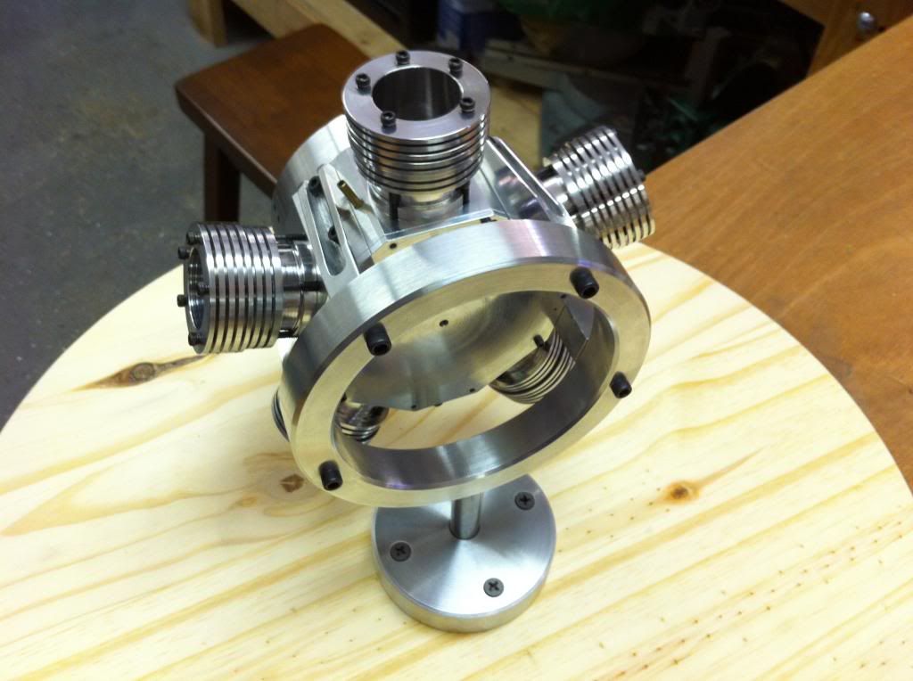
and, from the other side...


The motor mounts are pretty obvious, just carved out of 1/2" square ali; the circular mount is milled out from a 5" diameter 7075 billet, and the leftover center piece was used as the actual base mount (screwed to a Home-Depot-bought piece of 17" dia. circular piece of 3/4" ply), with a 3 1/2" length of stainless 1/2" dia. in between, screwed into the ali circle, and just sitting inside the 1/2" reamed center of the base mount. It seems secure, and rotates easily whenever shoved.

Glad your trip went well, Brian, and I hope it concludes safely and successfully. "Those heads" are waiting, and I'm a little envious...if for no other reason than, when I'm able to get my teeth into them, it'll mean that that *$@# crankshaft will be behind me...as it is that slab of tool steel is just laying there grinning at me, and I don't know if I'm at all equal to the task.

If not, I suppose there's more steel in the world.
 
Last edited:
G'day Mike,

I have received a reply from Kirk at Hemingway's and he says he wrote to you on March 29th. I guess you have some information coming snail mail.
I have pretty much decided to fit separate valve guides to the heads and am about to play around with some phosphor bronze and try to get an idea if this will be successful - will keep you informed.
By the way that stand is great and looks like it could be adapted to mount in an aircraft later.

Cheers Brian
 
Many thanks, Brian--I'll look forward to hearing back from Kirk.

Yes, my imaginary heads have guide-inserts in them too...I gather both brass and bronze have been used successfully.

My crankshaft is now in a state of becoming, though all it's become so far is a rough-sawn T-shaped piece of very tough steel, with some milled reference edges. My lathe has been looking at it nervously, and I've been wondering how to tactfully introduce them to one another when the time comes. It's going to be a bumpy relationship, at least in the beginning. I hope they don't talk among themselves when I'm not there.
 
G'day Mike , Steve and all,

I spent most of today messing around working out how to do the valve guides. this is my prototype.
Machined from 5/16" 544 phosphor bronze with hex. cut for 7mm socket so guides can be firmly tightened in head (I will also use loctite). The other diameters are 1/4" with the thread end 32 tpi same as for the glo-plug. I tapped a scrap piece of aluminium as a test and the guide pulled up nicely in it.
As I didn't have a 1/4" 32 die I had to cut the thread on the lathe but am going to purchase a die and grind one side to remove the lead in taper so that the thread can be finished with the die and cut right up to the flange.
Other alternatives would be to cut a thin recess next to the flange or use a thin precision ground washer to ensure the flange pulls up square in the head.
Fingers crossed but I think this is going to work OK so that now I have figured out (I hope) the procedure to make them it shouldn't take to long to make the 10 required.
How is your project coming along Steve?

Cheers all - Brian :noidea:

valveguide.jpg
 
Excellent work Brian.
I plan on building this at some point in time :D so this thread is very helpful.

On your valve guides, is there some reason you don't want to use valve cage assemlies? That is what I have in mind. It just seems an easier way to make sure everything is concentric. They could be put into the heads with locktite.

Ron
 
G'day Ron - Evening actually, thank you for you accolades and comments.
I did actually consider a valve cage assembly incorporating the valve seat but somehow I seem to like the idea of the guides doubly secure in the heads. I don't anticipate any concentricity issues as I intend to make a valve seat cutter that fits into the guides ensuring the valve seats are perfectly aligned and concentric with the guides.
Thats my story anyhow and I'm sticking to it (for now!) but as they say the best laid plans of mice and men are bound to go astray.

Cheers Ron and thanks again for your interest and comments - it is appreciated.*bang*
 
G'day all - all ten valve guides are now completed but modified from the original listed "prototype".
On reflection I was a bit concerned that possibly the valve spring could bind on the nut area at the bottom of the guide as there was little clearance so redesigned them with as smaller diameter 5.5mm nut cut at the top of the guide. There is now plenty of clearance for the valve spring along the full length of the guide. The total length of the guide is .590" including the thread.
I have just started on the heads and can see that they will keep me occupied for quite some time.
Cheers Brian - scratch.gif

valveguide2.jpg
 
Gorgeous work Brian...several centuries ago I knew an elderly tool and die guy, all gnarly and beery and surrounded by smoke, who didn't hold with any of the newfangled theories of metallurgy and mechanics and such but lived (most successfully) by the creed "If it looks right, it IS right."

That final guide just looks right.

For my part I'm still hacking away at the crankshaft, making slow progress, but some. It's still the busy season at work, so not much shop time, but maybe I'll have something to photograph by next weekend.

Never did hear back from Hemingway, so went ahead and spent the money...booked the trip and seats for a Stones concert (in Anaheim, overall a less hazardous deal than Vegas). Grinders will keep. Mick won't, at least not as long.

m
 
Back
Top