Duplex Vacuum, (Heinrici type stirling)

Home Model Engine Machinist Forum

Help Support Home Model Engine Machinist Forum:

This site may earn a commission from merchant affiliate links, including eBay, Amazon, and others.
Geeze Dean...I think its time to spring for some new M & M's ....that one looks a little worse for wear... :big: :big:

Hope you are continuing to feel better. I need to get busy here too...think i'm back on page two myself.

Bill
 
Very glad to see you're doing better.

The bushings look great...and small!

And now...that's right...I can't let you get away with it...

1) The M&M is obviously vintage 2002. And it's certainly been subjected to heat that exceeds the surface temperature of a palm. It is well past it's peak of flavor. Shame on you.
2) The tutu is for sale. Why would I give it away?

P.S. The standard M&M should be a 2008 Blue...but I don't have any. They were pretty good.
 
Hope you are continuing to feel better.
Why, thank you, Bill.
I ran out of fresh M&Ms 'til I get back into town. I don't wanna eat that last one, but give it a lick now and then. It's a "shop" M&M, so a little greasy. Not too bad, though.


Now Zee! Et tu, tu-tu frater?
Bein' under the weather, I haven't got to town recently to stalk up on the sacred candies. Tis my last one and my comfort piece. Even my battery powered Mr. Jelly Belly has run dry of Reagan fruits. Woe is me!

But wait... (sniff, sniff, sniff)... yonder wafts sensuous aromas of sponge cake and creamy filling. Ahhh, salvation! The long hidden Twinkie from the top shelf in the medicine cabinet beckons.
Glory and sweet relief, to last through long, cold night, ere dawn beckons shop owner to disgorge his supply of ovoid chocolates, jellied candies, and yes, fresh cake of sponge and goo. All will be made well and whole.

And they lived happily ever after. Well, the fat guy did, anyway.


Hi Dean bin quietly following your build, real nice work, :bow: sorry you've bin under the weather hope things start to improve for you.

Stew
 
Dean

it's good to see that you are starting to feel better, been down the "feel like crap" road myself just lately.... :big:

As to your medicinal sugar requirements... road trip time: Tim Horton's ( a chain of coffee & donut shops up here in the Great White North) have introduced a new treat.....

A slab of donut, coated with a generous layer of chocolate icing, said icing being there to glue on the coating of


wait for it


M&Ms ;D ;D ;D ;D

Cheers, Joe
 
Stew, thank you.
Joe D. A man after my own heart!

Well, I've gone from feeling crappy, up to just feeling a little cruddy, which is an improvement by
any measurement.
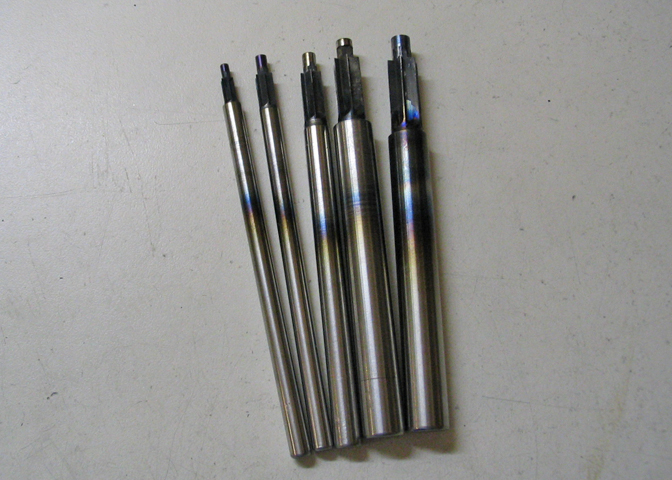
So, after messing up my cutter last time, I thought I should show it done up without any big goofs, and
maybe someone will find something useful.
Some of the members here know how to make such things well and proper. I know how to make
them so they work, but it may not be the best way to do it. It's A way to do it, and a way that
gives you a functioning cutter.

There are a few basics, and if you get them right, your cutter will usually work.
1) you need the cutting edges, obviously
2) you need a place for chips to escape, (flutes)
3) you need a relief of some sort behind the cutting edge, (or the edge will just rub)
4) it usually helps if cutting edges trail the centerline of the cutter during rotation
5) I'm not a tool and die maker


63.jpg


This time, end mill on the right side of things, three cuts are made, just over 1/2 the diameter deep,
(see #4, above), and with a feed on the X that will barely let the end mill take a nick out of the pilot.
The material is W-1 drill rod. O-1 will work as well, and I think actually holds an edge a little better, but
it's not as handy to work with indoors.

The depth of cut part, "just over 1/2 the diameter deep", refers to the cut as measured from the top
of the work piece down to where the cut ends. It needs to go just below the center line of the tool
blank. For this diameter, which is .375", I made the cuts .190" deep. You can use approximately
1% as your factor to figure how much over half the diameter you should go. It's a figure that
I know works for tools of diameters from 1/8" to 1/2". It may work for many other diameters. The
ones mentioned are in my actual experience.

That nick in the pilot is to make sure that what will be the cutting edge on the bottom of the cutter will
actually have an edge right up to the center of the pilot hole. Otherwise, it won't cut well right next to
the pilot hole.


64.jpg


Now I'm headed in the right direction, literally. Should have put a better finish on the larger diameter
when I turned up the blank, but this will still work fine. A better finish on the end would have left a
smoother finish at the bottom of the hole this cutter will make.


65.jpg


It's time to cut the clearances behind the cutting edges. The vise is slewed over about 7° to the
right. That's not a fixed number. Six to ten degrees would have been fine. Not too much of an angle
though, or there will be little support for the cutting edges.


66.jpg


The white arrow shows the edge that will do the cutting. Most of the material behind that has to be
backed off a bit, or the whole end of the cutter will just rub. That's the reason for setting the vise over
the 7 deg.
Then a small end mill is used to nibble away at the material behind the edge. I left about 1/32" of the
original edge intact. The brighter part behind the edge is the part that's been cut away. The part that
is removed, behind the cutting edge, has to be taken down right to the diameter of the pilot. It's okay
if you make a small flat spot on the pilot when doing this. Just use an end mill small enough so you
don't make a very large flat.


67.jpg


The white arrow points to a little nub that's left after the first relief cuts. That has to be removed yet. The red line is the cutting edge, just for reference.


68.jpg


Here, one of the nubs is about to be cut away. The point at the red arrow is where the last one has
just been removed. You can do what you want in the area behind the cutting edge, meaning, if you
have to cut into it a little to get rid of things like that nub, it's okay. Just don't mess up the cutting
edges, and it will work as it should.

Once this is done, the piece is hardened and tempered. I think that's been covered a number of times
on the forum, so won't repeat it unless someone asks.


70.jpg


After it's hard, the cutting edges are honed lightly just to get the burrs off and smarten up the cutting
edges. This is the only surface that was put to a stone. You need to use a hard, smooth Arkansas
stone for this kind of stuff. Not some grainy old whet stone.


71.jpg


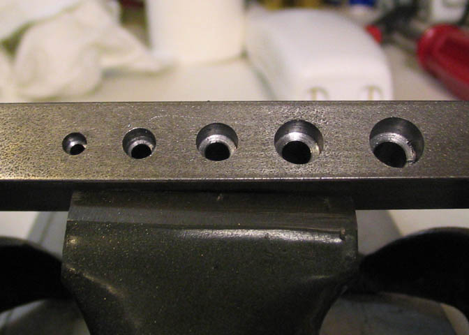
Works like a charm. The pilot on the cutter is used to center the bearing support, and then the recess
is cut to hold the bearing. I ran it at 500 rpm and let it have it's own way on the down feed.

The last thing for today is to ream the other two arms on the supports.


72.jpg


I'm just showing another way to do things, here. I don't mean it's anything new, but might get someone
out of a spot for lack of tooling, or if you own a small milling machine.

I need to ream the last two pilot holes to 5/16", but don't have a collet that size to fit my mill, and if I
use a drill chuck, there's not room for it mounted up under the spindle.
Reamers have a center hole in the chucking end, so I turned up a center that would fit up the spindle,
and into a collet I have available. Then I can hand turn the reamer with a tapping handle, and while
feeding down the spindle, ream the hole true.


73.jpg


Last shot of these things, (I think!). Goodness knows, everyone's seen enough of them.
The bronze bearings set in the holes that were run through with the factory reamer. The two
ball bearings fit into the pockets that were bored with the shop made cutter.

If there are questions, ask away.
Thanks again everyone!

Dean
 
Dean, Ime glad your wellness factor got bumped up a notch or two.

Thanks for the info on making the cutter.

How tight of a fit is the bearing in the pocket?

Kel
 
Thanks Kel.
The bearings just slip in. They're too small to take a press fit. They'd be damaged.

Dean
 
A little drop of blue Loctite won't do any harm. Keeps them from spinning but still easy to remove ;)
 
Deanofid said:
They're too small to take a press fit. They'd be damaged.

Dean

Ah Yes, I know this too well. I always wondered how you guys did it.

Noitoen said:
A little drop of blue Loctite won't do any harm. Keeps them from spinning but still easy to remove ;)

Very Good. I will have to impliment this method.

Thanks again.

Kel
 
Nice post Dean. Helps a lot when a post explains not just how to make a part but how to make the tool to make the part. It was very interesting.
 
Kel, I use just a dab of Locktite, too. Just a tiny smear on a spot on the outer housing. No need to coat
the whole thing. These go into blind holes, and I want to be able to remove them.

Zee, really glad you liked it!


Just did a little today, and went very slow at it. Should be back up to snuff in a few days now.

Two more rods yet to make, and also got a start on the crankshaft. The rods are of 1/16" aluminum
sheet, and I won't show much about them, since they are simple flat parts.


74.jpg


Showing how I get by without a large vise, here. When I have to cut things that won't fit into my small
vise, (which is just about everything), I clamp it down with a wood spacer beneath it, and one wood
spacer top of the piece, so the C clamps won't scar the metal. Then cut away, as in the shot above.


75.jpg


The two pieces were squared up in the mill. In the picture above, I'm making use of a short rule in place
of a parallel. Generally, any straight edge will have, you know... straight edges. I have parallels, but
none this thin, and this machinists rule does a fair job in a pinch.


76.jpg


That's it for today. The long pieces will be the piston rods, once they are shaped up. They form a
sandwich on either side of a couple of bushings. The crankshaft is a built up type. The short shafts are
drill rod faced to length for the crank, and the rectangular bits are for the crank throws. Only two
throws are needed, but I'm making two extras to use as a jig for assembling the crank pieces.
Might get to some more of this on Monday.


Thanks for having a look!

Dean
 
Coming along very well Dean. At first Ithought your red M&M had suffered some terrible deforming fate, but on second glance I see it a Jelly Belly instead. Trying to confuse us eh? :big:

Really though, this is a nice project and you are doing a great job on the build so I am hoping to learn some things from that as well. I enjoyed the section on making the cutter as well...have you used them on materials harder than aluminum?

Bill
 
Deanofid said:
I ran out of fresh M&Ms 'til I get back into town. I don't wanna eat that last one, but give it a lick now and then.

Tis my last one and my comfort piece. Even my battery powered Mr. Jelly Belly has run dry of Reagan fruits. Woe is me!

I'm thinking he ate (or licked away) that last M&M and found a Jelly Belly from a hoard hidden behind his Twinkies.

He's not trying to confuse us. He's trying to get away with something. I don't know what yet...but I don't trust him. ;D

I have to admit though...it's difficult to notice the edible candies when he keeps showing all that other shiny eye candy.
 
Dean, thanks for the tutorial on the counter bore cutter. I kind of knew the process, but it's always nicer to see one being made.

Chuck
 
b.lindsey said:
I enjoyed the section on making the cutter as well...have you used them on materials harder than aluminum?

Bill

Bill, I've used these on steel, too. I made the cutter to put the T-slots in my rotary table, and that was A36 HRS. I had to make two cutters to complete that job.
I've made many of them, including a set of countersinks for #2 thru #10 cap screws. All made from drill rod.

19.jpg


They work well in 1018 CRS:

20.jpg


Tool life on aluminum and brass is a long time. When used on steel, they have limited life. Keep the speed down, though, and they'll last long enough to be worth making.


Zee, you have such a suspicious mind. Hmmm... Skeletons in your closet?

Chuck, thanks for checking it out!

Dean
 
Hello all;
Some more work on the crankshaft today.


77.jpg


The crank throws are all drilled and reamed using a stop on the vise. After the two throws and two jig
pieces were reamed, I put a couple of pieces of drill rod through the holes in all of them, stacked like a
sandwich. Just to make sure the holes were positioned properly.


78.jpg


Some filing done on the two throws and rods to shape them up.


79.jpg


The two rods are fastened to their bushing using Locktite Threadlocker blue. While it sets up, the small
ends of the rods are held in time as shown above.


80.jpg


The two separate sides of the crank are jigged up like so to keep all the holes parallel. The pieces
actually being fastened are shown at the red arrows. The longer piece of drill rod in the assembly, and
the two square blocks are removed once the glue dries. For these pieces, I used Locktite Sleeve
Retainer. It's much stronger than the regular blue kind of Threadlocker.

After those pieces set up, the con-rod is fastened between them in a similar manner. I would prefer to
solder them, though the Sleeve Retainer will surely hold. Usually I would solder these up using two
longer pieces of drill rod through them, then cut out the part between the throws that would become
the longer crankshaft itself. I can see why Howell suggests to do it this way, though. Since the rod is
captive on the crank once it's all put together, there would be a very good chance of soldering the rod
bearing to the crank journal when trying to solder the throws to it, (to the journal, that is).

The chance for crank runout while doing it this way is increased, though. The finished piece has about .003"
on one end, which will show up as flywheel wobble. I think it can be straightened well enough. If not,
I'll be making this piece again.


81.jpg


There's today's assembly pic.

Thanks for looking in.

Dean

 
Very slick crankshaft construct. I suppose the throws could be pinned if there was a fear of them coming loose. Lotite is wonderful stuff.
Regards
Ernie J


Ernie, thanks for the nice comments.
I have a few engines that use pinned cranks, but not needed here, for sure. Sleeve retainer is tough stuff,
with a 3000 psi shear strength, so my puny stirling engine won't offer it any threats. ; )

Now, an apology to anyone who notices: I misspelled Loctite more than once. No "k" in Loctite. Okay.
And the second thing, the sleeve retainer wasn't the Loctite product at all. It's the Prematex version.
Sorry Loctite people. Sorry Permatex people. Sorry HMEM people. What a goof!

Dean


Latest posts

Back
Top