Design and build side-shaft hit and miss engine from bar stock

Home Model Engine Machinist Forum

Help Support Home Model Engine Machinist Forum:

This site may earn a commission from merchant affiliate links, including eBay, Amazon, and others.
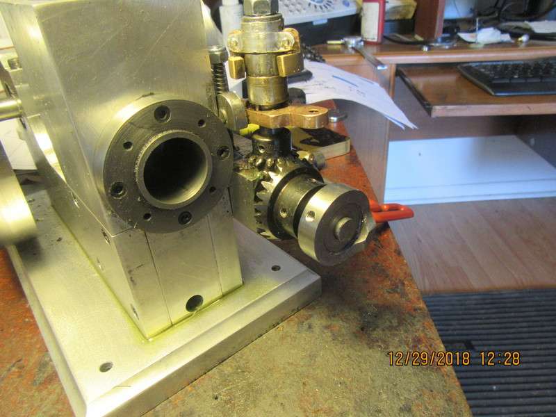
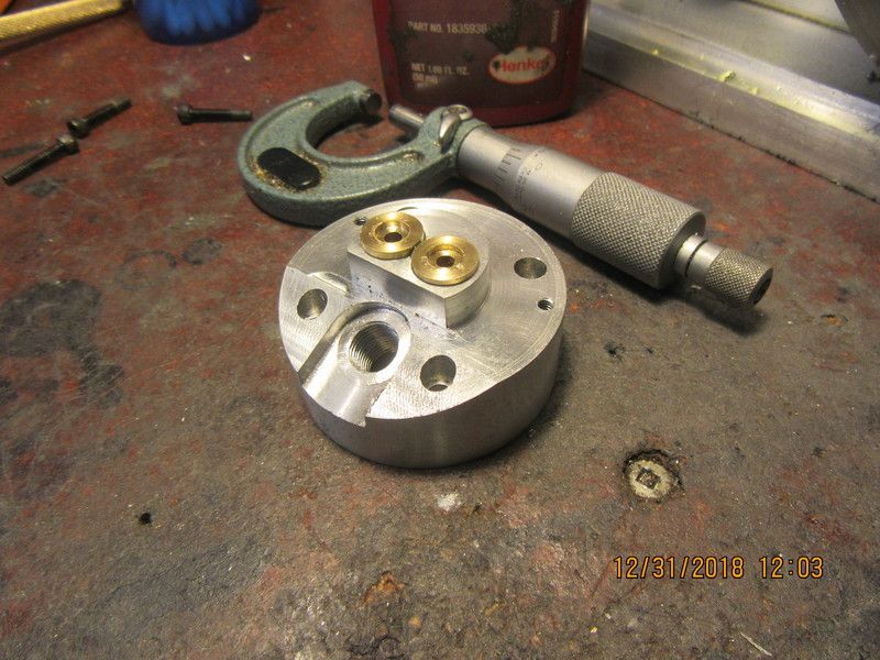
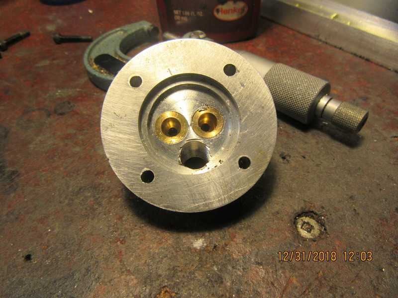
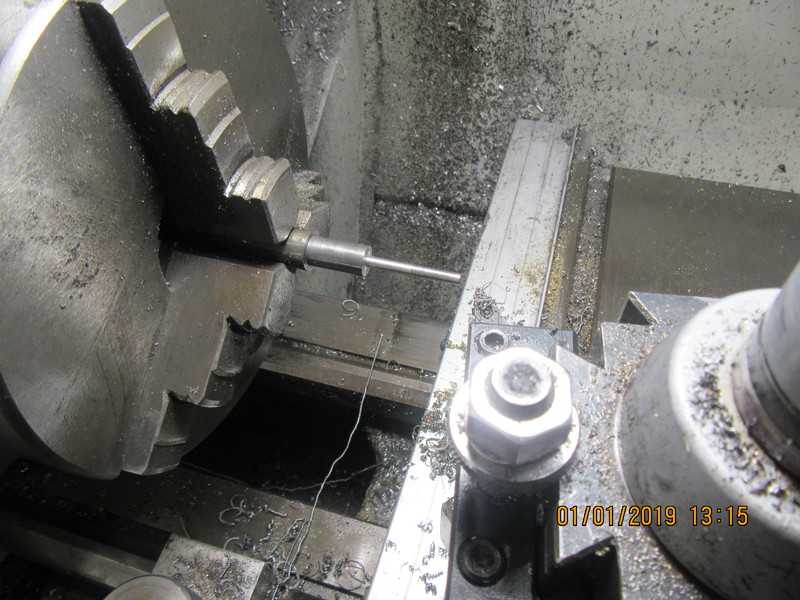
-And here is the face cam finished, roosting safely where it is intended to go. Will it work?--Well, probably. I won't know until everything else is finished and I try to start the engine. These little hit and miss engines are pretty forgiving.---Brian
fHpn9j.jpg
 
Man, I'm livin' large today!!! Finished the face cam this morning, laid down for my old man's nap this afternoon, then got up and made the ignition cam. And just as I finished the ignition cam, goodwife showed up from her part time job at the library and took me out to eat at A & W. Life don't get much better than that!!!
SwTeQ6.jpg
 
Looking great Brian.
I am so glad your a fast builder as I really am looking forward for this one to run.
Cheers
John
 
Brian, at the rate that you are getting this engine done, it will be finished before the end of the year. Still looking great and cant wait to see it run.
Happy New Year to you, your good wife and family from me and mine.
Cheers
Andrew
 
Brian
The build has taken some very interesting twists, enjoyed it all. I have a fab shop 2o miles from me it has a new owner and they will not sell anything but by the book. They get cutting on everything.
Have a Happy, Healthy New Year
Nelson
 
Guys, I greatly appreciate you stopping by and saying Hi. Sometimes it feels like I am posting into a vacuum. I have no doubts about the engine running. If there is an issue, I predict it will be in getting the governor driven lockout to engage successfully. Sometimes with things like this, computer modelling will take you only so far. You have to "build it and see if it works."
 
Guys, I greatly appreciate you stopping by and saying Hi. Sometimes it feels like I am posting into a vacuum. I have no doubts about the engine running. If there is an issue, I predict it will be in getting the governor driven lockout to engage successfully. Sometimes with things like this, computer modelling will take you only so far. You have to "build it and see if it works."

I'm sure there are many who read every post. I keep my mouth shut because I think I've probably not added anything worthwhile in the times I have posted a reply.

I'm waiting to see it run, like all the others.
 
Oh No, Definitely not posting into a vacuum Brian. I along with I suspect many others check on the progress daily. So, even if I don't post, (mostly for the same reason as CFLBob above) I do enjoy all your posts and hope one day to make one of these hit and missy engines.
Keep posting please,
I wanna see it run.
John B
 
It's no fun having an ignition cam if you don't have the rest of the parts that go with it. Today I made the ignition points mounting block and adjusting handle. I keep an old set of Dodge ignition points that I use for "set up" purposes only. Everything fits in behind the flywheel, which has been removed for this picture. My original design of the points mounting block allowed for adjusting the timing while the engine was running. I realized that I couldn't use the same method for this engine, but I redesigned the mounting block and put in two slotted adjustment holes which can be easily accessed thru the holes in the flywheel web--just not while the engine is running.
g3fuyH.jpg
 
A really good sign this evening!!---I filled the water reservoir with water and nothing appears to be leaking. There are six bolts which break thru into the water reservoir, and they were all coated with clear silicone on the threads before they were installed. The sides from which the cylinder enters and the side where it exits were both sealed with viton O-rings and silicone when the cylinder was installed. I am going to make a very fancy polished top from brass to fit the top of the reservoir, and either Loctite or J.B. weld it into place, and I had to be sure I had no leaks before doing this. I will leave it full of water overnight and hope there are no puddles around the engine when I get up tomorrow.
 
This morning I machined the valve cages from brass. These "cages" have a dual function. They guide the valve by way of the reamed center hole, and they also have the valve seat machined in them using a special tool after the Loctite has set up for 24 hours. They are machined to be very slightly larger than the 0.394" holes thru the cylinder head, and are pressed and loctited into the head. The inside of the holes in the head have been degreased using a q-tip and laquer thinners. No cutting oil was used when the valve cages were machined, so they don't need degreasing. Also in the picture, you will see a piece of cold rolled steel that I use for a "pusher" so that I don't deform the valve cages while pressing them into place in the cylinder head. There will be another hole thru the sides of these cages for the inlet and exhaust ports, but it will be drilled thru both cylinder head and valve guides after the Loctite has "set" for 24 hours.
wMq8IJ.jpg
 
Both valve cages are now pressed into place. At the last minute I decided not to use my arbor press, and just used my bench vise to push the cages into place. The "pusher" didn't get used. The holes in the cylinder head were reamed to 0.394". The valve cages were turned to 0.395" except for the shoulder. I seem to be getting better at this "press fit" business. The recess you see in the top/outside of the valve cages is in there to keep the valve springs centered when they are assembled with the valve which passes thru this guide.
c5av0x.jpg

tnrqtV.jpg
 
Today we are going to start the new year off with a valve tutorial. For all of you guys with years of experience, this will be kinda like teaching your grandma how to suck eggs. For all the new-bees following, this method has proven to be "tried and true" for me. There are two critical areas on a valve. The most critical is of course the valve face which seals against the seat in the valve cage. The second critical area is the shank of the valve itself. It must fit into a reamed hole in the valve cage, and "run true" without sticking or being sloppy. In the two attached pictures, you will see one short piece of scrap with a 0.125" hole drilled and reamed thru it. Why??--Because, as the valve is being turned down to be a "good sliding fit" in the valve cage, we need something with a very precise 0.125" diameter hole to
keep checking the size of the shank we are turning on the valve. This is an area where I have been burned before by taking measurements with a micrometer and trusting them to give me a "good sliding fit". With the 0.125" reamed hole in the piece of scrap, I can exactly replicate the hole in the valve caged which was reamed with the same reamer. I do NOT recommend using the brass valve cage as a checking guide. I have damaged brass valve cages in the past by doing that. The second picture shows a piece of 1/2" cold rolled in the 3 jaw chuck, with a portion of it turnmed to 0.375". Why--because no 3 jaw chuck has 0 runout. my chuck has about .003" total indicated runout, and I want the head of the valve to be perfectly concentric with the shank. Doing it this way ensures concentricity between valve stem and valve head.
JdYlL4.jpg

hwhSDw.jpg
 
When I make valves, I cut the valve seats in the valve cages to an included angle of 90 degrees with a special tool I will show in a later post. I like to make my valves with a 92 degrees included angle. This seems to work best for me when it comes to lapping the valves into their seats for an air tight seal.
rMaUAD.jpg
 
Last edited:
In order to cut this angle, the topslide is swung around until the protractor is showing 46 degrees. This essentially means turning the top slide almost completely around and locking it in that position. Now with the lathe set up like this, it means I can reduce the shank to the correct diameter, and then use the topslide to cut the 46 degree angle without changing any set-ups.
vruW26.jpg

eH6Vbb.jpg
 
Now we are at the stage where deflection becomes the enemy. Whatever the length of your valve-stem is, divide it by 3 and that becomes the length which you machine. I am using a brand new HSS cutter here, and taking 0.010" depth of cut. My target diameter is 0.135" diameter. When I'm getting close to the finished diameter, I reduce my depth of cut to 0.005", and taking the same cut over two or three times, because at this diameter, the work will spring away from the tool. I am leaving the part 0.010" oversize for a reason.
WXrd9W.jpg
 
Second verse-Same as the first. In this shot we have machined the second "third" of the full length. Again, remember to not take a great depth of cut (0.010", then 0.005" when you get close to the target diameter of 0.135"), and take repeat cuts at the same setting because of material spring-back. Also--If you do slip and let the diameter go lower than 0.125", you have ruined the part and will have to start over again. That is why we are leaving that 0.010" oversize, to give ourself a safety buffer.
SpyOgA.jpg
 
Back
Top