Design and build side-shaft hit and miss engine from bar stock

Home Model Engine Machinist Forum

Help Support Home Model Engine Machinist Forum:

This site may earn a commission from merchant affiliate links, including eBay, Amazon, and others.
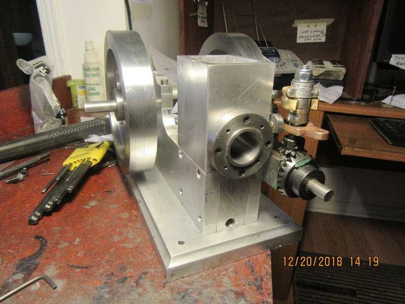
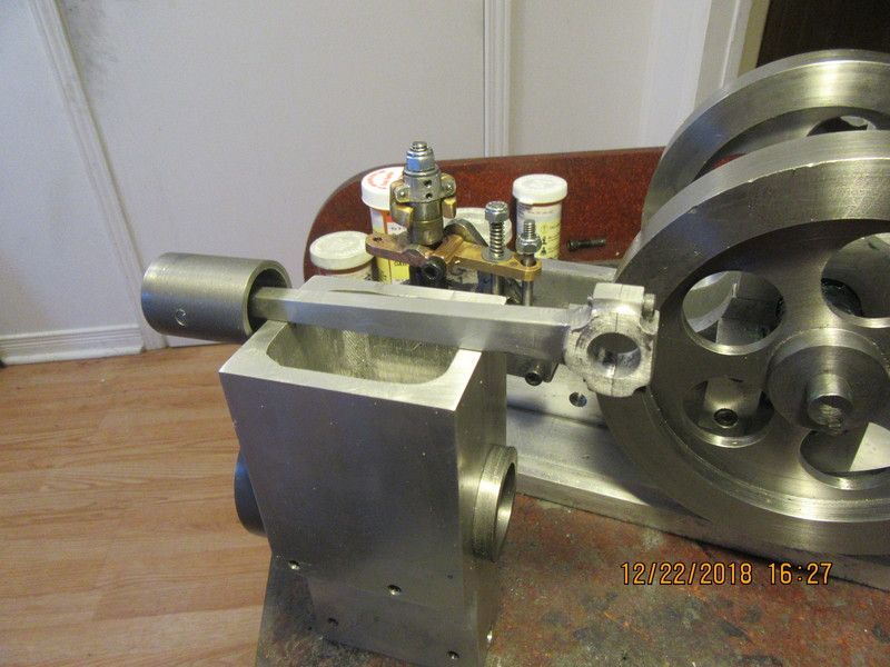
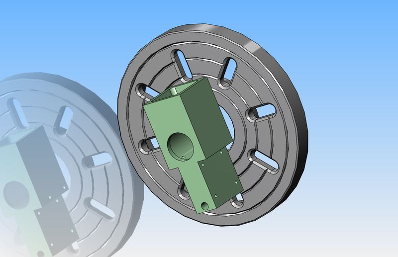
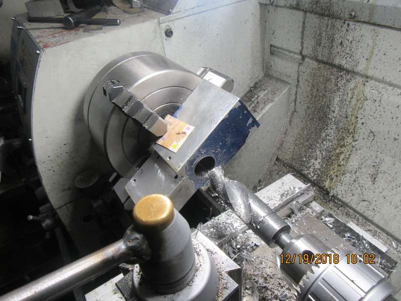
I am just in the initial stages of marking out cut lines on the piece of 2 1/2" square piece of aluminum which will become my cooling tower. Since the bore will be somewhat complicated by being larger internally than at the outside ends, it can't be done with a conventional boring head. So--I dragged the model over onto my lathe faceplate. this immediately shows me two things. #1--the part will fit okay for turning, as it doesn't stick out beyond the edges of the faceplate. #2---I don't want to trim it to length until after I have bored it. By leaving it full length, I can put a bolt thru the top (above what is shown as the open end of the water reservoir) to bolt it to the faceplate, then trim it to length after it has been bored.
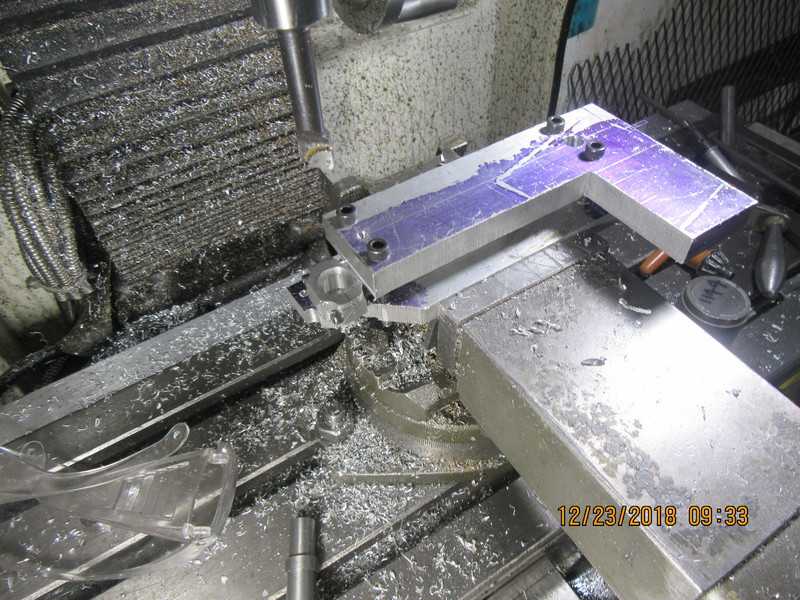
vIDu7l.jpg
 
After what seemed like an awful lot of bandsawing and milling, we have the part which becomes the cylinder mount and water reservoir. It fits very well where I intended it to. You can see a line scribed about 3/4" down from the top which is actually the height that it will end up at. For now I will leave that 3/4" on and drill a hole thru it to use as a mount for that end when I attach it to the faceplate of my lathe. There will be a hole thru the other end for the gas-line from my tank to run thru. It will do for the bolted connection at the other end when I attach it to the faceplate.
476Q97.jpg

rQn0ds.jpg
 
My first engine to build from bar stock and 1/8 cold rolled steel I did buy the fly wheels and spent many hours machining them to the scale of a International M
 

Attachments

  • IMG_2818.JPG
    IMG_2818.JPG
    27 KB · Views: 219
Well, the good news is that out of 10 tapped holes in the water reservoir, all of them lined up with the holes in the sideplates and governor block, and all the bolts went in with no fuss. That always kind of surprises me and makes me feel good. I finished up the design work that was going to keep me busy until Christmas, so should be able to get a bit more done on the engine now. I think probably tomorrow I will mount the water reservoir/cylinder mount on either the faceplate (or maybe the 4 jaw) on my lathe and put the cylinder hole in it.
 
The other good thing is that the flyweights on the governor don't fly out far enough to smack the corner of the reservoir. The CAD showed that they would miss it, but not by very much. I wasn't terribly concerned, because if they had I can cut some material away from that corner without breaking through to the inside of the reservoir. Regardless of what the CAD shows me, I like to actually see the parts made in metal and assembled to confirm it.
o1chqb.jpg
 
Rather than mess around with critical press fits between the cylinder and the water reservoir to prevent leaks, I am going to o-ring the water reservoir same as I did on the Rockerblock engine. This demands only a "close sliding fit" between the cylinder and the water reservoir, and with a 1/16" o-ring and some silicone applied during assembly, it seals very well and doesn't leak a drop of water.
EPMNPJ.jpg
 
I decided to use the four jaw chuck rather than the faceplate. I figured the part was less apt to move when held in the four jaw chuck. In this shot I have just used my largest drill (1") to get all the way thru. You will also see that this time I decided to use some cardboard under the chuck jaws. I generally forget that and then have to contend with the marks that the jaws leave afterwards. Now I will switch over to my boring tools and finish boring out the cylinder hole and the larger diameter that surrounds it for a "water gallery". I will also put in the o-ring grooves in each side before I tear down the set-up.
gt6Mro.jpg
 
Laydieeees and Gentlemennn--to amaze and delight you, we have--TADA---a cylinder, finished and bolted in place. It isn't honed nor lapped yet on the inside. That will happen after the piston gets made.
dDxeWU.jpg
 
This morning I had five hours of "real" work. This afternoon I machined a cast iron piston. It is completely finished other than external lapping. It is larger than the cylinder bore by .002" to .003". I have ordered some #8 to 12 micron diamond lapping compound, and it should be here before Christmas.
gjIxs9.jpg
 
Today I will machine a con rod. My initial idea was to make one from bronze, but none of my suppliers have bronze in stock in the size I wanted. That's okay. I will build one from aluminum. I have many engines with 6061 aluminum connecting rods and they work just fine. I like to build my con rods as one piece and then cut the caps loose with a slitting saw, bolt them back together, then drill and ream the "big end" hole.
VOjMsg.jpg
 
In this shot we have the second step of machining the connecting rod. The first step was to machine a piece of 1/2" aluminum stock down from 1/2" to 7/16". The small end has the 3/16" hole drilled and reamed. All of the other holes are what form the radii between surfaces on the rod.
1g54lA.jpg
 
So---Today was con-rod day. I can't believe it, but it has taken the entire day to make this little beastie. I wanted to post a pic of it installed on the engine, but it doesn't fit. How can that be? It fits perfectly on a piece of 1/2" cold rolled round stock. Out comes the micrometer, and guess what.--The center journal on my one piece crankshaft isn't 0.500". It is 0.520" diameter. POOP!!! I'm not even going to try to set that crankshaft up in the 4 jaw chuck again. I will now figure out how to set up the con-rod in my mill and open the big end up to 0.520". Don't let all of those pill bottles in the background disturb you. I get a fresh supply of them full of pills every month, and the old bottles are perfect containers for teensy weensy little bolts and nuts.
XaKUqX.jpg
 
So here we are. Two things going on here. One shows the con-rod sandwiched between two scrap pieces of aluminum plate and set up in the vice to be bored out to 0.520" diameter to match the oversized crankshaft journal, and a second picture of the con-rod in place in the engine assembly. There is currently no piston in there---I'm waiting for some diamond lapping paste.
7i5Q6a.jpg

wxmdXr.jpg
 
Back
Top